TD350 Series VFD Basic operation instructions
-61-
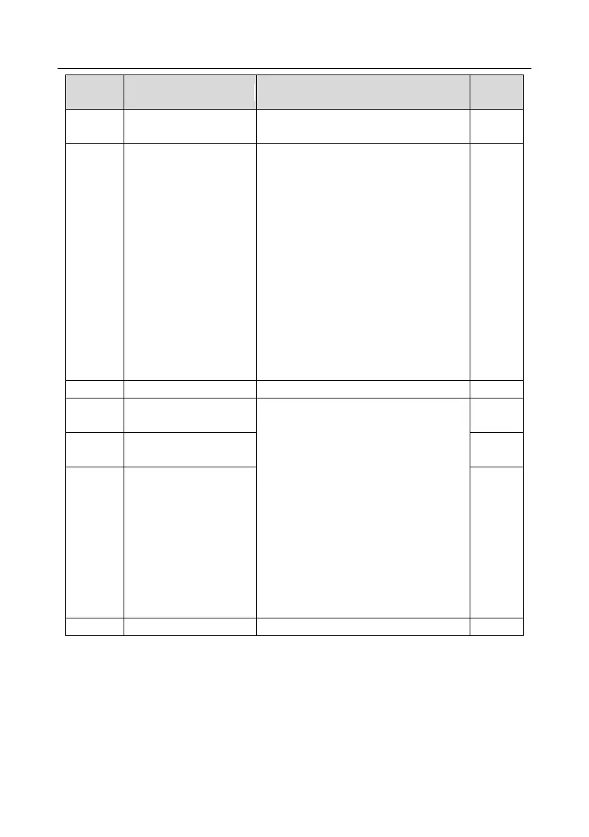
Detailed parameter description
Control optimization setting
Ones place: Reserved
0: Reserved
1: Reserved
Tens place: Reserved
0: Reserved
1: Reserved
Hundreds place: ASR integral separation
enabling
0: Disabled
1: Enabled
Thousands place: Reserved
0: Reserved
1: Reserved
Range: 0x0000–0x1111
High-frequency ACR
proportional coefficient
In the closed-loop vector control mode
(P00.00=3), when the frequency is lower
than the ACR high-frequency switching
threshold (P03.39), the ACR PI parameters
are P03.09 and P03.10; and when the
frequency is higher than the ACR
high-frequency switching threshold
(P03.39), the ACR PI parameters are
P03.37 and P03.38.
Setting range of P03.37: 0–20000
Setting range of P03.38: 0–20000
Setting range of P03.39: 0.0–100.0% (in
relative to the maximum frequency)
High-frequency ACR
integral coefficient
ACR high-frequency
switching threshold
5.5.4 V/F (SVPWM) control mode
TD350 VFD also carries built-in V/F (SVPWM) control function. V/F (SVPWM) mode can be used in
cases where mediocre control precision is enough. In cases where a VFD needs to drive multiple
motors, it is also recommended to adopt V/F (SVPWM) control mode.
TD350 VFD provides multiple kinds of V/F curve modes to meet different field needs. Users can
select corresponding V/F curve or set the V/F curve as needed.