4-22
If the emergency signal is released before the inverter stops completely, the inverter still carries
out the emergency stop. The 01-09/01-10 determines the action of the error terminal. If
01-09/01-10=0: the fault is not enabled when the external emergency signal input. If
01-09/01-10=8, the fault is actuated when the emergency signal input.
6. 01-00~05=9 : Base Block
The inverter immediately stops output, and the motor does a Coast with flashing B.B.
8. 01-00~05=10 : Main/sub Control Signal Selection
When External multifunction input terminals are off, the inverter is operated by 00-03.
When External multifunction input terminals are on, the inverter is operated by 00-04.
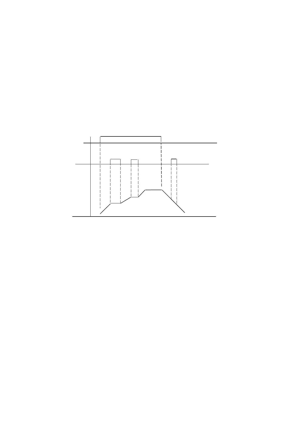
9. 1-00~05=11 : Disable acceleration and deceleration
The acceleration and deceleration action is unavailable until the disable signals are released.
The action is illustrated in the graph below:
10. 1-00~05=12, 13: UP/DOWN Function (Actual ACC/DEC time is based on the setting) :
(1) 00-05/00-06 = 3 to use the UP/DOWN Function. The other frequency signals are ignored.
(2)Set 01-07=0 and 01-08=0. The inverter accelerates to the preset value of 03-01 when in
RUN, and then it maintains a constant speed. As the inverter receives either the UP/DOWN
command, it will accelerate / decelerate until the command is released. The inverter runs at
the speed setting at the time of release. The inverter will ramp stop or Free-Fun stop which
is determined by the 04-01 as long as the inverter receives the STOP command. The
frequency at Stop time will be stored in03-01. The UP/DOWN KEY is invalid when the
inverter is stopped. It is necessary to use the Keypad to modify the preset parameters.
(3)Set 01-08 = 1, the inverter will operate from 0Hz when the operation terminal is ON. The
action of UP/DOWN is the same as above. The inverter will ramp stop or free-run stop as
determined by 04-01 setting when it receives the Stop Command. The next operation will
start at 0 Hz.
(4)UP/Down Signals simultaneously pressed are invalid
(5)01-07≠ 0, the inverter accelerates to the setting of 03-01 and maintains speed. When the
UP/Down terminal is on, setting frequency is the value 03-01±01-07, and the inverter will
accelerate/ decelerate to frequency 03-01. The upper frequency limit and lower frequency
limit also restrict the operation. If the signal of UP/ DOWN is maintained over 2 seconds,
the inverter will begin to accelerate/ decelerate. If 01-07=0, the operation is the same, until
the UP/ DOWN signal is released. Please refer to the time diagram of 01-07.
Note : Operation Switch is OFF, the command of disable
Operation
Si
nal
Disable
ACC/DEC
Output
Fre
uenc
Figure 4-8 Acceleration and deceleration Prohibit
 Loading...


