4-29
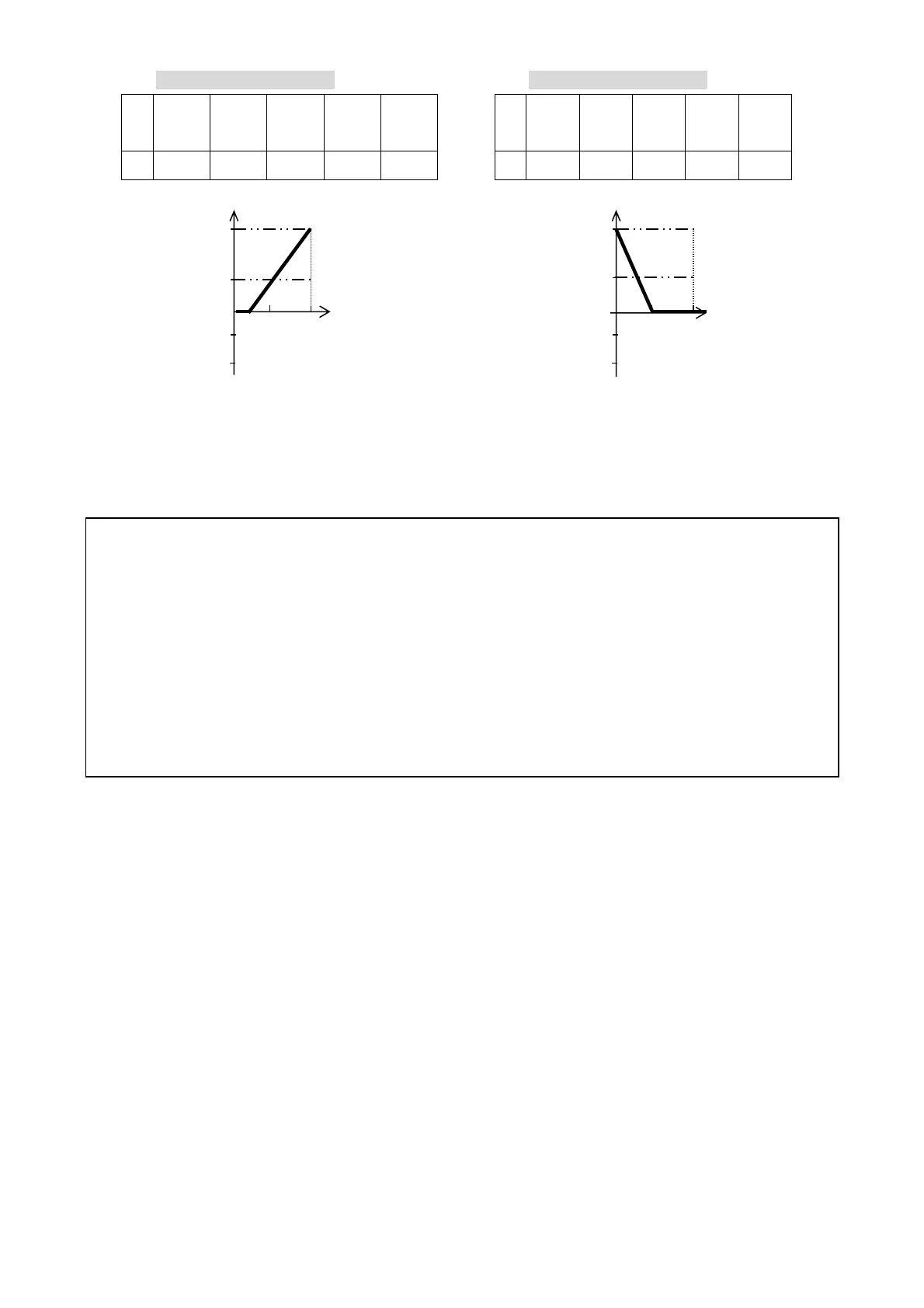
The setting of figure 4-18C : The setting of figure 4-18D :
2-02
/2-08
2-03
/2-09
2-04
/2-10
2-05
/2-11
2-09
2-02
/2-08
2-03
/2-09
2-04
/2-10
2-05
/2-11
2-09
E 100% 20% 1 0 100% F 100% 50%
1
1 100%
1) The inverter reads the average value of A/D signals once per (02-01/02-07 x 4ms). Set scan
intervals according to possible noise interference in the environment. Increase 02-01/02-07 in an
environment with noise interference, but the response time will increase accordingly.
Multifunction analog output control
02-12 :Analog Output Voltage Mode
0 : Output frequency 1 : Frequency Setting
2 : Output voltage 3 : DC Bus Voltage 4 : Output current
02-13 : FM+ Gain(%) 0 ~ 1000
02-14 : FM+ Bias(%) 0 .0~ 100.0
02-15 : FM+ Bias Selection 0 : positive 1 : Negative
02-16 : FM+ Slope 0 : positive 1 : Negative
02-17 : Analog Signals Fluctuation of Filter Coefficients =1 ~ 100
User can adjust the filter coefficients depend on the analo
si
nals fluctuation on stable
situation. If the si
nals fluctuation is heav
, the filter coefficients can be hi
her, but the
resolution of analog signals will be lower at the same time.
1. The multifunction analog output terminal of the terminal block , is 0~10Vdc analog output. The
output type is determined by the02-12. The output voltage level can be scaled by parameter 02-13 to
suit external meters and peripherals.
Note: the max output voltage is 10V due to hardware of the circuit. Use only devices that require a
maximum of 10V signal.
Upper Frequency Limit
(00-07=60)
Upper Frequency Limit
(00-07=60)
Hz
V
60Hz
30Hz
0Hz
E
2V
(4mA)
10V
(20mA)
Bias
0%
-50%
-100%
Hz
V
60Hz
30Hz
0Hz
F
5V
10V
(20mA)
Bias
-0%
-50%
-100%
Figure 4-16 Analog scaling examples
 Loading...


