4-34
2. 04-09=1and the inverter is set external terminal controlled (00-03/00-04=1), if the run switch is
ON as power is supplied, the inverter will not auto start and the display will flash with STP1.
It is necessary to turn OFF the run switch and then ON to start normally.
04-10 : Delay-ON Timer (Seconds) : 1.8 ~ 300.0 second
As power on and 04-09=0, the inverter will perform auto restart in the setting time for delay.
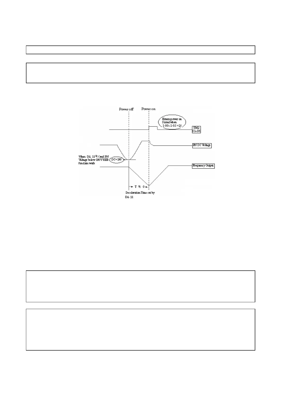
04-11 : Kinetic Energy Back-up Deceleration Time (S)
= 0.0 : Disable
= 0.1~25.0 : KEB Deceleration Time
04-11 = 0 KEB function disable 04-11≠ 0 KEB function enables
Example : 220V system
※
Note:
1. When 04-11≠0, the momentary power loss and Restart is disabled, the inverter will do KEB
Function.
2. When input power is turned off, CPU detects the DC bus Voltage and as soon as DC bus Voltage
becomes lower than190V (220V system) or 380V (440V system), then the KEB function is
activated.
3. When KEB function is enabled, the inverter decelerate to zero by 04-11, and the inverter stop
4. IF the power on signal enabled during the KEB function, the inverter accelerate to original
frequency.
04-12 : Lower Limit of Power Voltage Detect = 150.0 ~ 210.0/300.0 ~ 420.0
04-13 : DC Injection Brake Level(%) @start = 0.0 ~150.0
04-14 : DC Injection Brake Time (Seconds) @start = 0.0 ~ 25.5
04-15 : DC Injection Brake Start Frequency (Hz) @Stopped = 0.10 ~ 10.00
04-16 : DC Injection Brake Level (%)@Stopped = 0.0 ~ 150.0
04-17 : DC Injection Brake Time (Seconds)@stopped = 0.0 ~ 25.5
04-18 : Braking transistor action level 200V: 320~400 380V: 550~800
1. 04-17 / 04-15is the action time and start frequency of DC braking, as graph below:
Figure 4-18 KEB function diagram
 Loading...


