4-45
09-13 : Allowable Integration Error Margin (Unit) (1 Unit = 1/8192) =0 ~ 100
09-13=0 ~ 100% unit value : Restart the tolerance after the integrator reset to 0.
09-14 : Sleep Frequency Level(Hz) = 0.00 ~ 400.00
09-15 : Sleep Function Delay Time(S) = 0.0 ~ 25.5
09-16 : Wake up frequency Level(Hz) = 0.00 ~ 400.00
09-17 : Wake up function Delay Time(S) = 0.0 ~ 25.5
PID SLEEP MODE:
09-00=1(PID Enable)
02-06=0(PID FEEDBACK Enable)
00-05=PID setting frequency source (Target Value)
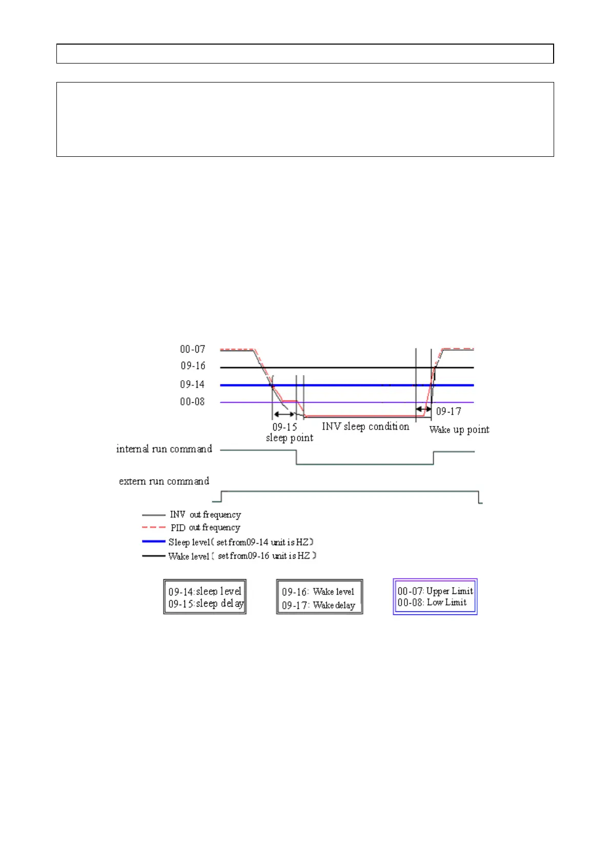
09-14 : set the sleep threshold frequency, Unit:HZ
09-15 : set the time for sleep delay, Unit: sec
09-16 : set the wake threshold frequency, Unit:HZ
09-17 : set the time for wake delay, Unit: sec
When PID output frequency is less than the sleep threshold frequency and exceeds the time of sleep
delay, the inverter will decelerate to 0 and enter PID sleep mode.
When PID output frequency is larger than the Wake threshold frequency for Wake start the inverter will
reactivate and enter PID wake mode. The time diagram is as follow:
Figure 4-27 PID sleep wake mode diagram
 Loading...


