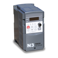
N3 Drive Operations Manual
A (Advanced) Parameter Details; A091 Cont. & A092 – A097 62
(D) A091 = 0001 - 0003: If the inverter stops and re-starts, it will continue running from the unfinished step,
according to the setting of A091.
= 0004 - 0006: If the inverter stops and re-starts, it will begin a new cycle and continue running according
to the setting of A091.
Run
Command
Output Frequency
Run Run
Stop
Continue running
from unfinished step
t
Run
Command
Output Frequency
Run Run
Stop
Begin a new cycle
t
A091 = 0001 - 0003 A091 = 0004- 0006
Auto Run Cycle with Interrupt
Fig. 19.15
0000: positive
0001: negative
0000: positive
0001: negative
AIN & AI2 signal verification
Scan Time
1.) A094 = 0000: (AIN Bias selection positive) 0V (0mA) corresponds to the lower frequency limit, and 10V (20mA)
corresponds to the upper frequency limit.
2.) A094 = 0001: (AIN Bias selection negative) 10V (20mA) corresponds to the lower frequency limit, and 0V (0mA)
corresponds to the upper frequency limit.
3.) AI2 / S6 (PID feedback signal)
When A154 = 0000 (0 – 10 V / 0 – 20mA):
Output frequency (SW2 set to I) = I x (b005) / 20; when I ≥ 0
Output frequency (SW2 set to V) = V x (b005) / 10; when VI ≥ 0
When A154 = 0001 (2 – 10 V / 4 – 20 mA):
Output frequency (SW2 set to I) = (I-4 )x (b005)/16; when I ≥ 4 (Output frequency =0; when I<4)
Output frequency (SW2=V) = (V-2) x (b005)/8; when V ≥ 2 (Output frequency =0; when V<2)
Cont.

 Loading...


