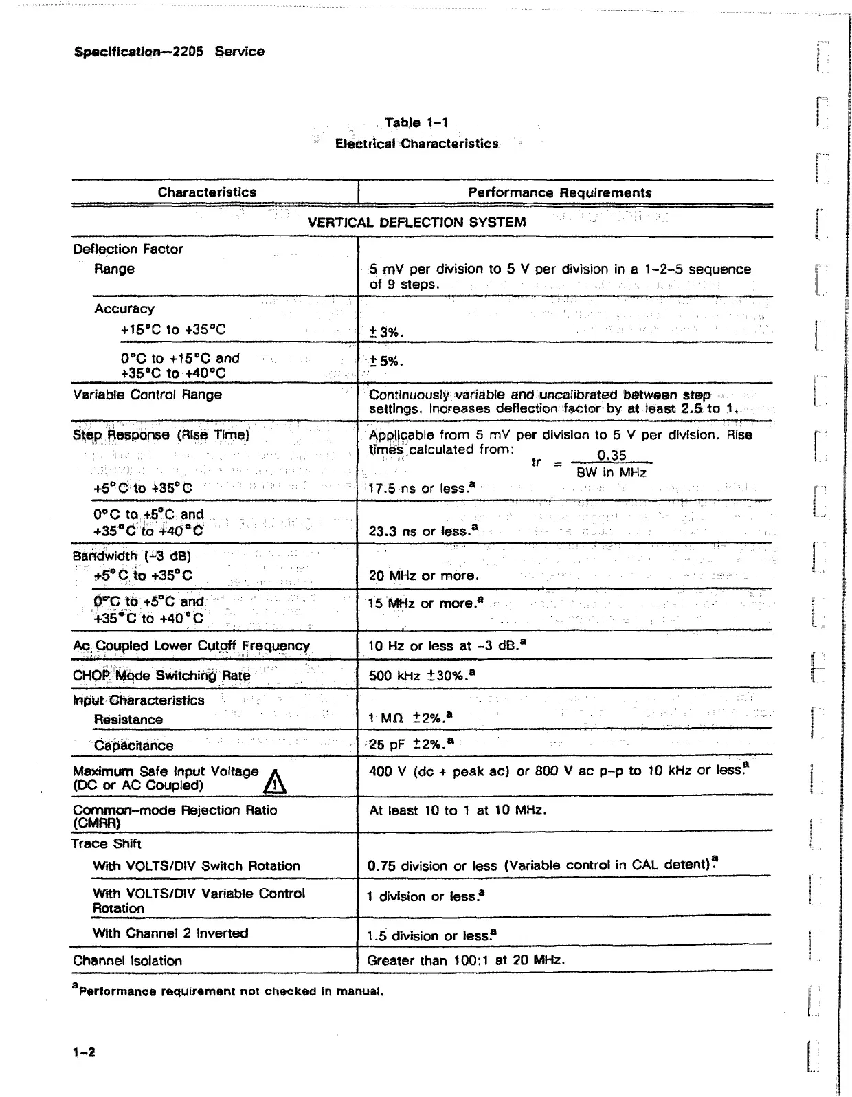
Specification—2205 Service
Table 1-1
Electrical Characteristics
Characteristics
Performance Requirements
VERTICAL DEFLECTION SYSTEM
Deflection Factor
Range
5 mV per division to 5 V per division in a 1-2-5 sequence
of 9 steps.
Accuracy
+15°C to +3S°C
±3%.
0°C to +15°C and
+35°C to +40°C
±5%.
Variable Control Range Continuously variable and uncalibrated between step
settings. Increases deflection factor by at least 2.5 to 1.
Step Response (Rise Time)
+5°C to +35° C ■-
Applicable from 5 mV per division to 5 V per division. Rise
times calculated from: q gg
tf “ BW in MHz
17.5 ns or less.8
0°C to +5°C and
+35 °C to +40 °C
23.3 ns or less.®
Bandwidth (-3 dB)
+5° C to +35° C
20 MHz or more.
0°C to +5°C and
+35° C to +40 °C
15 MHz or more.8
Ac Coupled Lower Cutoff Frequency 10 Hz or less at -3 dB.8
CHOP Mode Switching Rate
500 kHz ±30% 8
input Characteristics
Resistance
i M n ±2%.*
Capacitance
25 pF ±2%.®
Maximum Safe Input Voltage a
(DC or AC Coupled) / ! \
400 V (dc + peak ac) or 800 V ac p-p to 10 kHz or less?
Common-mode Rejection Ratio
(CMRR)
At least 10 to 1 at 10 MHz.
Trace Shift
With VOLTS/DIV Switch Rotation
0.75 division or less (Variable control in CAL detent)?
With VOLTS/DIV Variable Control
Rotation
1 division or less.8
With Channel 2 Inverted
1.5 division or less?
Channel Isolation
Greater than 100:1 at 20 MHz.
Performance requirement not checked in manual.
1-2