Maintenance-2205 Service
2. Check Associated Equipment
Before proceeding, ensure that any equipment
used with the instrument is operating correctly.
Verify that input signals are properly connected and
that the interconnecting cables are not defective.
Check that the ac-power-source voltage to all
equipment is correct.
To avoid electrical shock, disconnect the instru
ment from the ac power source before making a
visual inspection of the internal circuitry.
3. Visual Check
Perform a visual inspection. This check may
reveal broken connections or wires, damaged com
ponents, semiconductors not firmly mounted,
damaged circuit boards, or other clues to the cause
of an instrument malfunction.
WARNING I
■ ■■ ■■■■■ ■ ■I
Dangerous potentials exist at several points
throughout this instrument. If it is operated
with the cabinet removed, do not touch
exposed connections or components.
4. Check Instrument Performance and
Adjustment
Check the performance of either those circuits
where trouble appears to exist or the entire instru
ment. The apparent trouble may be the result of
misadjustment. Complete performance check and
adjustment instructions are given in Sections 4 and 5
of this manual.
5. Isolate Trouble to a Circuit
To isolate problems to a particular area, use any
symptoms noticed to help locate the trouble. Refer
to the troubleshooting charts in the Diagrams sec
tion as an aid in locating a faulty circuit.
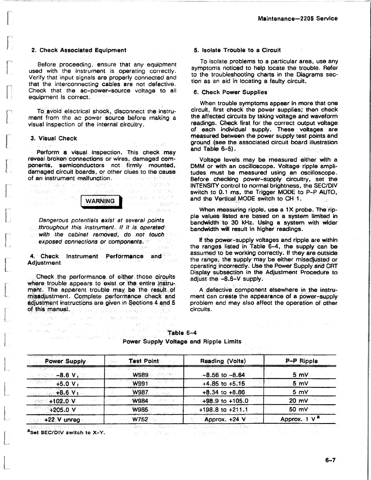
6. Check Power Supplies
When trouble symptoms appear in more that one
circuit, first check the power supplies; then check
the affected circuits by taking voltage and waveform
readings. Check first for the correct output voltage
of each individual supply. These voltages are
measured between the power supply test points and
ground (see the associated circuit board illustration
and Table 6-5).
Voltage levels may be measured either with a
DMM or with an oscilloscope. Voltage ripple ampli
tudes must be measured using an oscilloscope.
Before checking power-supply circuitry, set the
INTENSITY control to normal brightness, the SEC/DIV
switch to 0.1 ms. the Trigger MODE to P-P AUTO,
and the Vertical MODE switch to CH 1.
When measuring ripple, use a IX probe. The rip
ple values listed are based on a system limited in
bandwidth to 30 kHz. Using a system with wider
bandwidth will result in higher readings.
If the power-supply voltages and ripple are within
the ranges listed in Table 6-4, the supply can be
assumed to be working correctly. If they are outside
the range, the supply may be either misadjusted or
operating incorrectly. Use the Power Supply and CRT
Display subsection in the Adjustment Procedure to
adjust the -8 6-V supply.
A defective component elsewhere in the instru
ment can create the appearance of a power-supply
problem and may also affect the operation of other
circuits.
Table 6-4
Power Supply Voltage and Ripple Limits
Power Supply
Test Point
Reading (Volts)
P-P Ripple
. V,
W989 -8.56 to -8.64
5 mV
+5<0 y ,
W991 +4.85 to +5.15
5 mV
. . , : ::v : '^ ; r r : + 8 , 6 ' V i .
W987 +8.34 to +8.86
5 mV
:<:i!:r'!+1S2,6.V '
W984
+98.9 to +105.0
20 mV
+205 0 V
W985
+198.8 to +211.1
50 mV
+22 V unreg
W752
Approx. +24 V
Approx. 1 V a
aSet SEC/DIV switch to X-Y.