2213 Operators
BEAM FIND
button; the display should remain within
the viewing area.
5.
Set the Channel 1 AC-GND-DC switch to AC.
6. Observe that the display is centered approximately
at the center horizontal line.9. Adjust the AUTO INTENSITY control counterclock-
wise until the display disappears.
7.
Set the CH 1
VOLTS/DlV
switch to 0.1 (IX) and
observe that a 2-division vertical display appears.
10. Press in and hold the BEAM FIND push button;
the display should reappear. Release the BEAM FIND
button and adjust the AUTO INTENSITY control to
desired display brightness. 8. Rotate the CH
1
VOLTS/DIV
Variable control
fully counterclockwise.
Using the Vertical Section
1.
Set the Channel
1
AC-GND-DC switch to GND.
9. Observe that minimum vertical deflection occurs
when the
VOLTS/DlV
Variable contol is fully counter-
clockwise.
2. Adjust the trace to the center horizontal graticule
line.
IO. Rotate the CH
1
VOLTS/DIV
Variable control
fully
clockwise
to the CAL detent.
3. Set the Channel 1 AC-GND-DC switch to DC.
4. Observe that the bottom of the display remains at
the center horizontal graticule line (ground reference).
11.
Select
CH 2 VERTICAL MODE and again perform
preceding steps 1 through 10 using Channel
2
controls.
Performance should be similar to Channel 1.
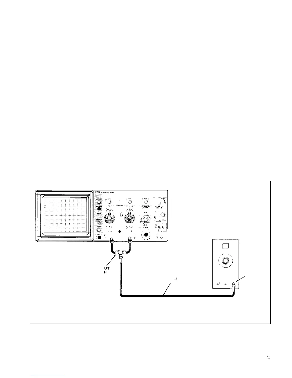
CALIBRATION
GENERATOR
DUAL-INP
COUPLE
AMPL
OUTPUT
50
!2
CABLE
/
3397-10
Figure 9. Initial setup for instrument familiarization procedure.
12
 Loading...


