2215A S erv ice
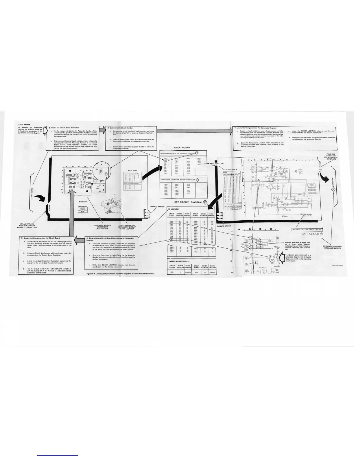
To identify any component
mounted on a circuit board and
to locate that component in the
appropriate schematic diagram
Locate the Circuit Board Illustration
In the instrument identify the Assembly Number of the
circuit board in question. The Assembly Number is usually
printed on the upper left corner of the circuit board on the
component side
In the manual locate and pull out tabbed page whose title
corresponds w ith the Assembly Number of the circuit
board Circuit board assembly numbers and board
nomenclature are printed on the back side of the tabs
(facing the rear of the manual)
w
2. Determine the Circuit Number
..
Compare the circuit board w ith its illustration and locate
the desired component by area and shape on the illustra
tion.
Scan the taNe adjacent tothe Circuit Board Illustration and
find the Circuit Number of the desired component.
b
V
c.
Determine the Schematic Diagram Number in w hich the
component is located.
A6 CRT BOARD
3. Locate the C ompo nent on the Schem atic Diagram
a. Locate and pull out tabbed page whose number and title
correspond with th e Schematic Diagram Number just
determined in the table. Schematic diagram nomenclature
and numbers are printed on the front side of the tabs
(facing the front of the manual).
Scan the Component Location Table adjacent to the
schem atic diagram and fin d the Grcuit Number of the
desired component
Under the SCHEM LOCATION column, read the grid
coordinates for the desired component.
Using the Circuit Number and grid coordinates, locate the
component on the schematic diagram.
CO MP ONE NTS LO CAT ED ON SC HEMAT IC D IAG RA M ^
O T t " " I
: ii« ii ® 4 J»iu '" ' _
» * > :
;»» t>: *.» I-MI
^ ^ t C 6 0 3 ) - —
C6 7I
C 6I5
C 6I6
M B
W c a ts
W C 6I9
C62 4
C62 6
" C641
C M3
C651
0606
06 10
06 15
06 45
06 56
06 65
m i m u i
R625
R62 6
R627
S
CO MP ONEN TS L OCA TED ON SCH EM ATIC DIA GR AM
C67 0
06 70
R67 7
C6 7I
06 72
R67 9
C67 3
06 73
R680
C68 0
C681
R671
U61 7
P603
R67 3
U6 18
P607
R67 4
U6 19
0669 R67 S
PULL OUT
PAGE TABS
FOR SCHEMATIC
DIAGRAMS
COMPONENT
CRT CIRCUIT DIAGRAM
ASSEMBLY NUMBER
AND CIRCUIT
BOARD NAME
ILLUSTRATION FOR
INSTRUMENT CIRCUIT
BOARD LOCATION
Locate the Com p o nent on the Circuit Board
In th e manual, locate and pull out the tabbed page whose
title and Assembly Number correspond w ith the desired
circuit board. This in form ation is on th e back side of the
tabs.
Using th e Circuit Number and grid coordinates, locate the
component on the Circuit Board Illustration.
In th e circuit board location illu stration, dete rmine the
location of the circu it board in the in strument.
Find the circuit board in the instrum ent and com pare it
w ith its illu stration in the manual to locate the desired
com ponent on the board.
4. D ete rmine the C ircu it Board Illustration and Component
Location
a. From the schematic diagram, determine the Assembly
Number of the circuit board on which the component is
mounted This information is boxed and located in a corner
of the heavy line that distinguishes the board outline.
Scan the Component Location Table for the Assembly
Number just determined andfm d theG rcu it Number of the
desired component.
Under the BOARD LOCATION column, read the grid
coordinates for the desired component
Figure 9-3. Locating components on schematic diagrams and circu it board Illustrations.
A6 ASSEMBLY 1 ^ ^
/
CI RCU IT
SC HEM
BO ARD C IRCUIT
SC HEM
BO ARD
NU MB ER
LO CAT ION LOC ATIO N N UMBE R
LO CATION
LO CAT ION
( C603
ic ) - —-
___
1G
06 65
1G IB
06 68 2G 28
C61 2
7C
3E
C61 5
7C
30
R60 4 -». ^ ac IE
C61 6
2C
3C
P60S
C61 7
70
30
P60 6
4E
hT——
C61 8 7E
3E
R60 9
4E
20
C6 19 6E 3C
R6 10
7B
3E
C62 4 4 f
30 R 614 7 C
30
C6 26
7G
20
R61 6 1C
30
C632
_
___
(C64 3
30
4 8 ^
R6 25
7f
20
C651
3€
38
7 f 20
*6 27
10
----
4E
7C
20
30 TP624
3B
20
70 3 0
3€
3B
U6 15
10 3C
CHASSIS MOUNTED PARTS
CI RCU IT
SC HE M
BO AR D
CI RCU IT SC HEM B OA RD
NUM BE R
LO CA TION
LO CATIO N
NU MB ER
LO CA TIO N LO CAT ION
L6 35 51
CHASS IS
V6 35 6J CHA SSIS
SCHEMATIC DIA GRAM
NAME AND NUMBER
To identify any component in a
schematic diagram and to locate
that component on its respective
circuit board.
<35 16 81 * 2 06 33