Maintenance—2215A Service
27. Reconnect P9001 and P9002 to the Main circuit
board (removed in step 8).
28. Insert the POWER switch extension-shaft assembly
into the front panel (from the rear). Push the POWER switch
to the ON lock position and align the extension shaft with
the switch shaft. Press them together gently until they snap
into place.
29. Reinstall the FOCUS control shaft assembly (re
moved in step 6).
30. Reconnect the connectors to the Attenuator and
Timing circuit boards (removed in step 5).
31. Resolder five wires from the Filter circuit board to
the Main circuit board (unsoldered in step 4).
32. Reinstall the Power-Supply shield and plastic power-
supply cover (see “Power-Supply Shield” reinstallation
procedure).
33. Reinstall the Alt Sweep circuit board (see “Alt
Sweep Circuit Board” reinstallation procedure).
34. Reconnect the B DELAY TIME POSITION poten
tiometer connector (P9644) to the Main circuit board
(disconnected in step 1).
REPACKAGING FOR SHIPMENT
If the instrument is to be shipped to a Tektronix Service
Center for service or repair, attach a tag showing: owner
(with address) and the name of an individual at your firm
that can be contacted. Include complete instrument serial
number and a description of the service required.
Save and reuse the package in which your instrument
was shipped. If the original packaging is unfit for use or not
available, repackage the instrument as follows:
Surround the instrument with polyethylene sheeting to
protect its finish. Obtain a carton of corrugated cardboard
having a carton test strength of 275 pounds and having
inside dimensions of no less than six inches more than the
instrument dimensions. Cushion the instrument by tightly
packing three inches of dunnage or urethane foam between
carton and instrument, on all sides. Seal carton with ship
ping tape or industrial stapler.
SELECTABLE COMPONENTS
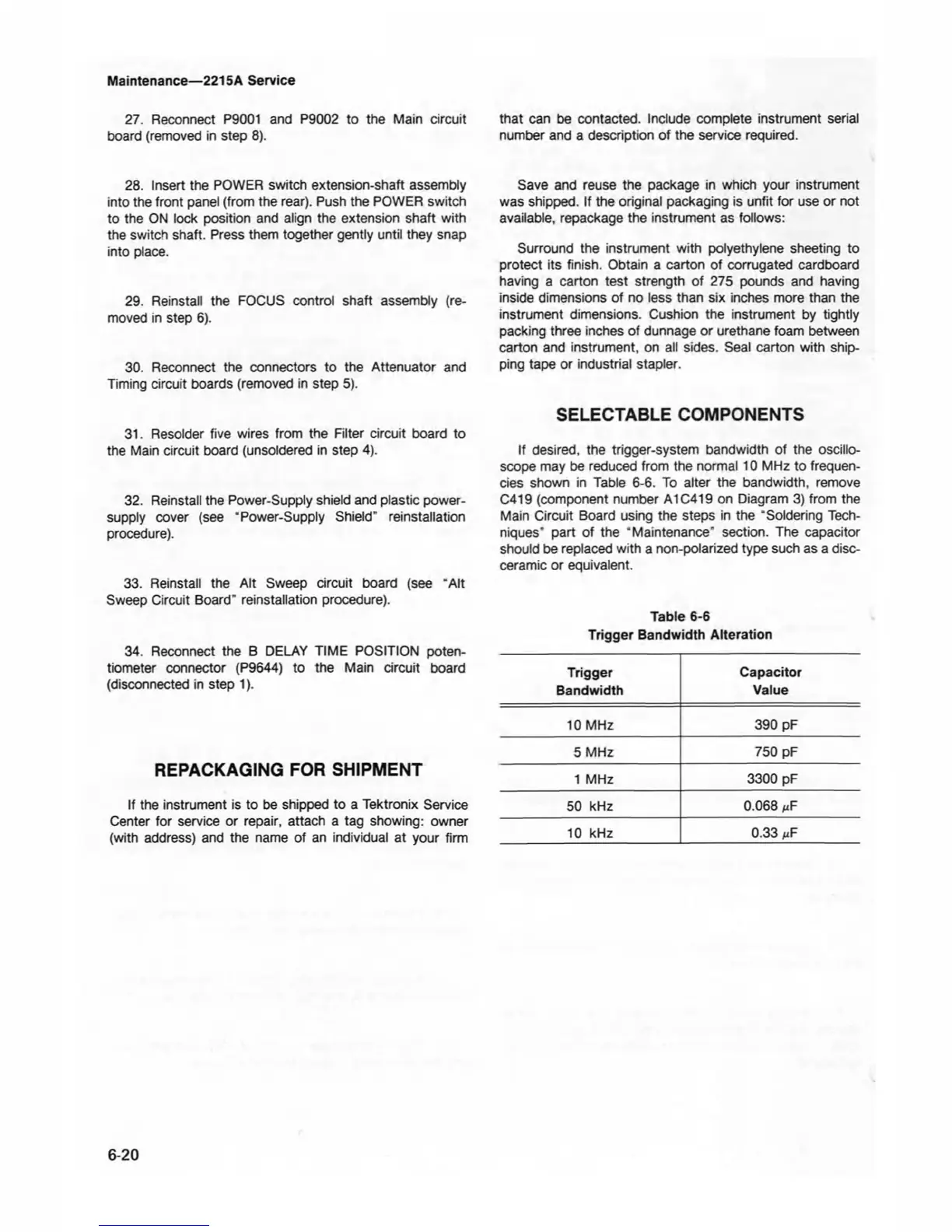
If desired, the trigger-system bandwidth of the oscillo
scope may be reduced from the normal 10 MHz to frequen
cies shown in Table 6-6. To alter the bandwidth, remove
C419 (component number A1C419 on Diagram 3) from the
Main Circuit Board using the steps in the “Soldering Tech
niques” part of the “Maintenance" section. The capacitor
should be replaced with a non-polarized type such as a disc-
ceramic or equivalent.
Table 6-6
Trigger Bandwidth Alteration
Trigger
Capacitor
Bandwidth
Value
10 MHz
390 pF
5 MHz
750 pF
1 MHz
3300 pF
50 kHz
0.068
nF
10 kHz
0.33
nF
6-20