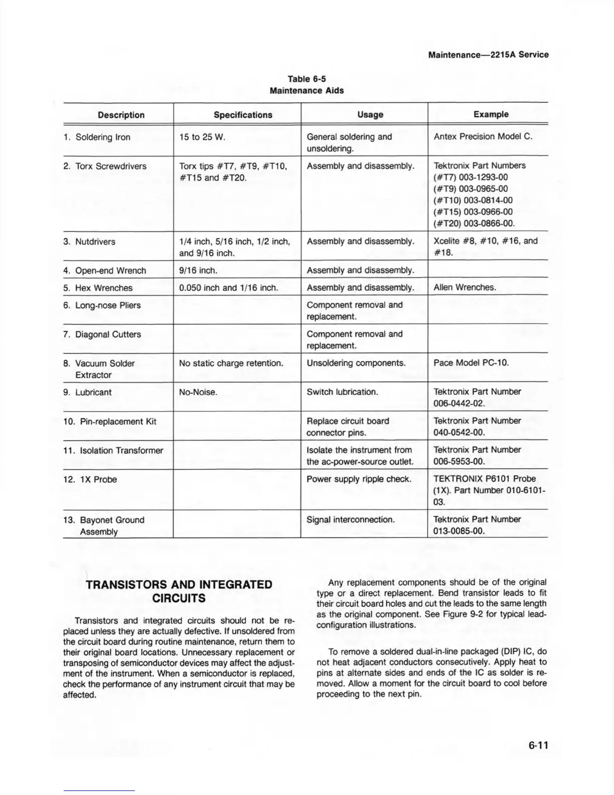
Table 6-5
Maintenance Aids
Maintenance—2215A Service
Description Specifications
Usage
Example
1. Soldering Iron 15 to 25 W.
General soldering and
unsoldering.
Antex Precision Model C.
2. Torx Screwdrivers
Torx tips #T7, #T9, #T10,
#T15 and #T20.
Assembly and disassembly.
Tektronix Part Numbers
(#T7) 003-1293-00
(#T9) 003-0965-00
(#T10) 003-0814-00
(#T15) 003-0966-00
(#T20) 003-0866-00.
3. Nutdrivers
1/4 inch, 5/16 inch, 1/2 inch,
and 9/16 inch.
Assembly and disassembly.
Xcelite #8, #10, #16, and
#18.
4. Open-end Wrench
9/16 inch.
Assembly and disassembly.
5. Hex Wrenches
0.050 inch and 1/16 inch. Assembly and disassembly.
Allen Wrenches.
6. Long-nose Pliers
Component removal and
replacement.
7. Diagonal Cutters
Component removal and
replacement.
8. Vacuum Solder
Extractor
No static charge retention.
Unsoldering components. Pace Model PC-10.
9. Lubricant No-Noise.
Switch lubrication.
Tektronix Part Number
006-0442-02.
10. Pin-replacement Kit
Replace circuit board
connector pins.
Tektronix Part Number
040-0542-00.
11. Isolation Transformer
Isolate the instrument from
the ac-power-source outlet.
Tektronix Part Number
006-5953-00.
12. IX Probe
Power supply ripple check.
TEKTRONIX P6101 Probe
(IX). Part Number 010-61 QI-
03.
13. Bayonet Ground
Assembly
Signal interconnection.
Tektronix Part Number
013-0085-00.
TRANSISTORS AND INTEGRATED
CIRCUITS
Transistors and integrated circuits should not be re
placed unless they are actually defective. If unsoldered from
the circuit board during routine maintenance, return them to
their original board locations. Unnecessary replacement or
transposing of semiconductor devices may affect the adjust
ment of the instrument. When a semiconductor is replaced,
check the performance of any instrument circuit that may be
affected.
Any replacement components should be of the original
type or a direct replacement. Bend transistor leads to fit
their circuit board holes and cut the leads to the same length
as the original component. See Figure 9-2 for typical lead-
configuration illustrations.
To remove a soldered dual-in-line packaged (DIP) 1C, do
not heat adjacent conductors consecutively. Apply heat to
pins at alternate sides and ends of the 1C as solder is re
moved. Allow a moment for the circuit board to cool before
proceeding to the next pin.
6-11