Operating Instructions—2215A Service
4. Verify proper fuse value (1.0 A, 250 V, slow blow).
5. Reinstall the fuse (or replacement fuse) and the fuse-
holder cap.
INSTRUMENT COOLING
Always maintain adequate instrument cooling. The venti
lation holes on both sides of the instrument cabinet and on
the rear panel must remain free of obstruction.
CAUTIO N
FOR C0NTIRUE0 FIRE PROTECTION
REPLACE ONLY WITH SPECIFlEO
TYPE ANO RATED FUSE DISCONNECT
POWER INPUT BEFORE REPLACING FUSE
/
LINE VOLTAGE RANGE
FUSE 250V
90 250VAC
1A SLOW
00 NOT REMOVE
COVER REFER
SERVICING TO
0UALIFIE0
PERSONNEL
POWER
MAX WATTS 40
MAX VA 70
FREQ 48 44 0 to
CAUTION
TO AVOIO ELECTRIC
SHOCK. THE POWER
CORO PROTECTIVE
GROUNOING CONDUCTOR
MUST BE CONNECTED
1 TO GROUNO
EXT Z AXIS INPUT
I0K Q POSITIVE GOING
INPUT OECREASES
INTENSITY
S VOLT P P CAUSES
NOTICEABLE
MODULATION AT
NORMAL INTENSITY
5 30 V PEAK
TEKTRONIX. INC . BEAVERTON. OREGON. U S A
u
POWER
CORD
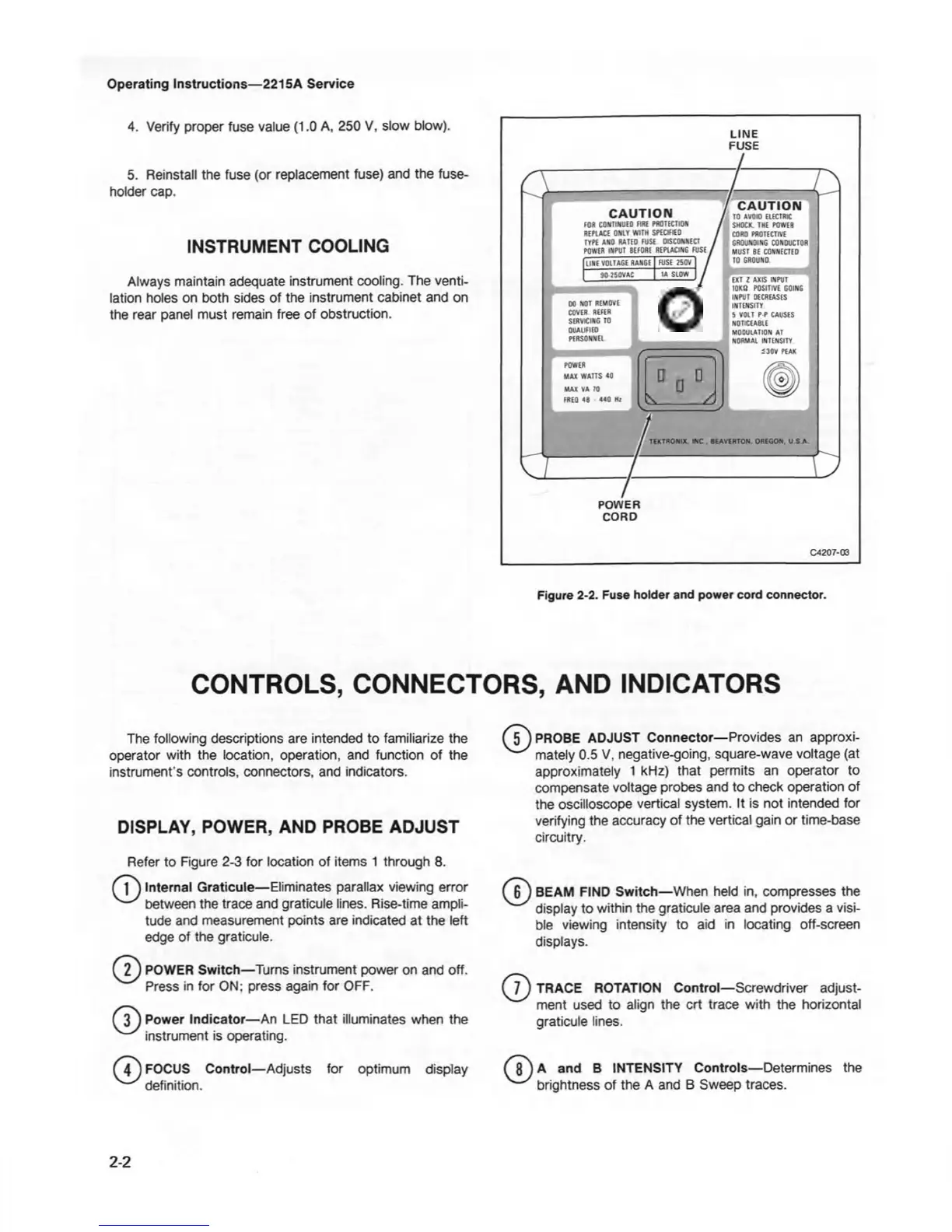
Figure 2-2. Fuse holder and power cord connector.
CONTROLS, CONNECTORS, AND INDICATORS
The following descriptions are intended to familiarize the
operator with the location, operation, and function of the
instrument's controls, connectors, and indicators.
DISPLAY, POWER, AND PROBE ADJUST
Refer to Figure 2-3 for location of items 1 through 8.
f 1 ) Internal Graticule— Eliminates parallax viewing error
between the trace and graticule lines. Rise-time ampli
tude and measurement points are indicated at the left
edge of the graticule.
f
2 j
POWER Switch—Turns instrument power on and off.
Press in for ON; press again for OFF.
f 3^ Power Indicator—An LED that illuminates when the
'
^
instrument is operating.
(4 j FOCUS Control— Adjusts for optimum display
^~' definition.
Mj)PROBE ADJUST Connector— Provides an approxi-
^ mately 0.5 V, negative-going, square-wave voltage (at
approximately 1 kHz) that permits an operator to
compensate voltage probes and to check operation of
the oscilloscope vertical system. It is not intended for
verifying the accuracy of the vertical gain or time-base
circuitry.
( 6 J BEAM FIND Switch— When held in, compresses the
y display to within the graticule area and provides a visi
ble viewing intensity to aid in locating off-screen
displays.
TRACE ROTATION Control— Screwdriver adjust
ment used to align the crt trace with the horizontal
graticule lines.
^8^ A and B INTENSITY Controls— Determines the
'
'
brightness of the A and B Sweep traces.
2-2