2215A Service
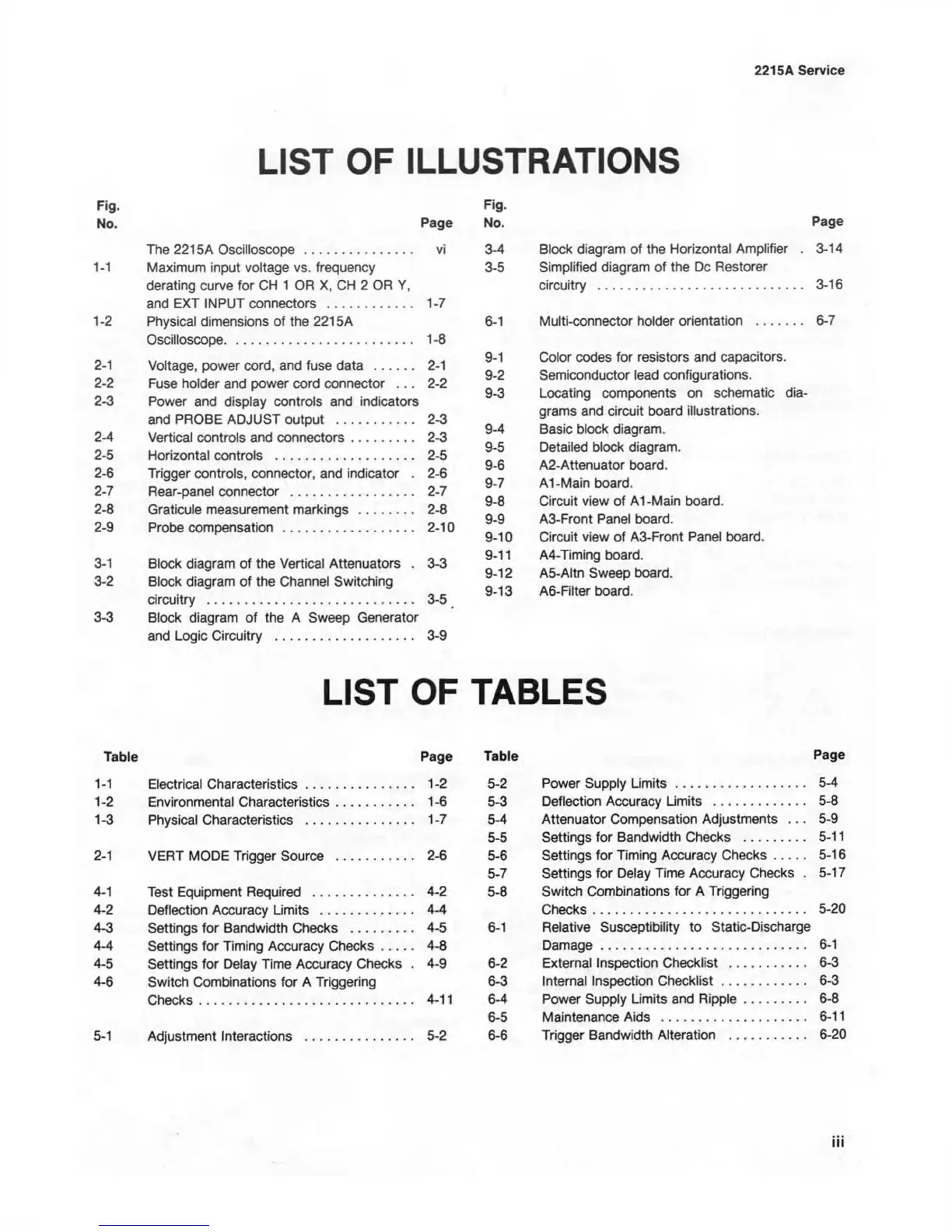
LIST OF ILLUSTRATIONS
Fig-
No. Page
The 2215A Oscilloscope
.............................
vi
1-1 Maximum input voltage vs. frequency
derating curve for CH 1 OR X. CH 2 OR Y,
and EXT INPUT connectors
.......................
1-7
1- 2 Physical dimensions of the 2215A
Oscilloscope
...................................................
1-8
2- 1 Voltage, power cord, and fuse data
..............
2-1
2-2 Fuse holder and power cord connector .. . 2-2
2-3 Power and display controls and indicators
and PROBE ADJUST output
.....................
2-3
2-4 Vertical controls and connectors
.............
2-3
2-5 Horizontal controls ....................................... 2-5
2-6 Trigger controls, connector, and indicator . 2-6
2-7 Rear-panel connector ................................... 2-7
2-8 Graticule measurement markings ................ 2-8
2- 9 Probe compensation .................... 2-10
3- 1 Block diagram of the Vertical Attenuators . 3-3
3-2 Block diagram of the Channel Switching
circuitry
........................................................
3-5
3-3 Block diagram of the A Sweep Generator
and Logic Circuitry ...................................... 3-9
Fig.
No.
Page
3-4
Block diagram of the Horizontal Amplifier .
3-14
3-5
Simplified diagram of the Dc Restorer
circuitry ........................................................
3-16
6-1
Multi-connector holder orientation
............
6-7
9-1
Color codes for resistors and capacitors.
9-2 Semiconductor lead configurations.
9-3
Locating components on schematic dia
grams and circuit board illustrations.
9-4 Basic block diagram.
9-5
Detailed block diagram.
9-6
A2-Attenuator board.
9-7 Al-Main board.
9-8
Circuit view of Al-Main board.
9-9
A3-Front Panel board.
9-10
Circuit view of A3-Front Panel board.
9-11
A4-Timing board.
9-12
A5-Altn Sweep board.
9-13
A6-Filter board.
LIST OF TABLES
Table Page
1-1 Electrical Characteristics
................................
1-2
1-2 Environmental Characteristics
........................
1-6
1- 3 Physical Characteristics ................................. 1-7
2- 1 VERT MODE Trigger Source
.......
2-6
4-1 Test Equipment Required
..............................
4-2
4-2 Deflection Accuracy Limits
............................
4-4
4-3 Settings for Bandwidth Checks
....................
4-5
4-4 Settings for Timing Accuracy Checks
..........
4-8
4-5 Settings for Delay Time Accuracy Checks . 4-9
4- 6 Switch Combinations for A Triggering
Checks
..........................................................
4-11
5- 1 Adjustment Interactions
...............
5-2
Table Page
5-2 Power Supply Lim its................................ 5-4
5-3 Deflection Accuracy Limits
..........................
5-8
5-4 Attenuator Compensation Adjustments .. . 5-9
5-5 Settings for Bandwidth Checks
..................
5-11
5-6 Settings for Timing Accuracy Checks
....
5-16
5-7 Settings for Delay Time Accuracy Checks . 5-17
5- 8 Switch Combinations for A Triggering
Checks.................................................... 5-20
6- 1 Relative Susceptibility to Static-Discharge
Damage
...................................................
6-1
6-2 External Inspection Checklist
......................
6-3
6-3 Internal Inspection Checklist
...................
6-3
6-4 Power Supply Limits and Ripple
.............
6-8
6-5 Maintenance Aids
.........................................
6-11
6-6 Trigger Bandwidth Alteration
......................
6-20