Performance Check Procedure—2215A Service
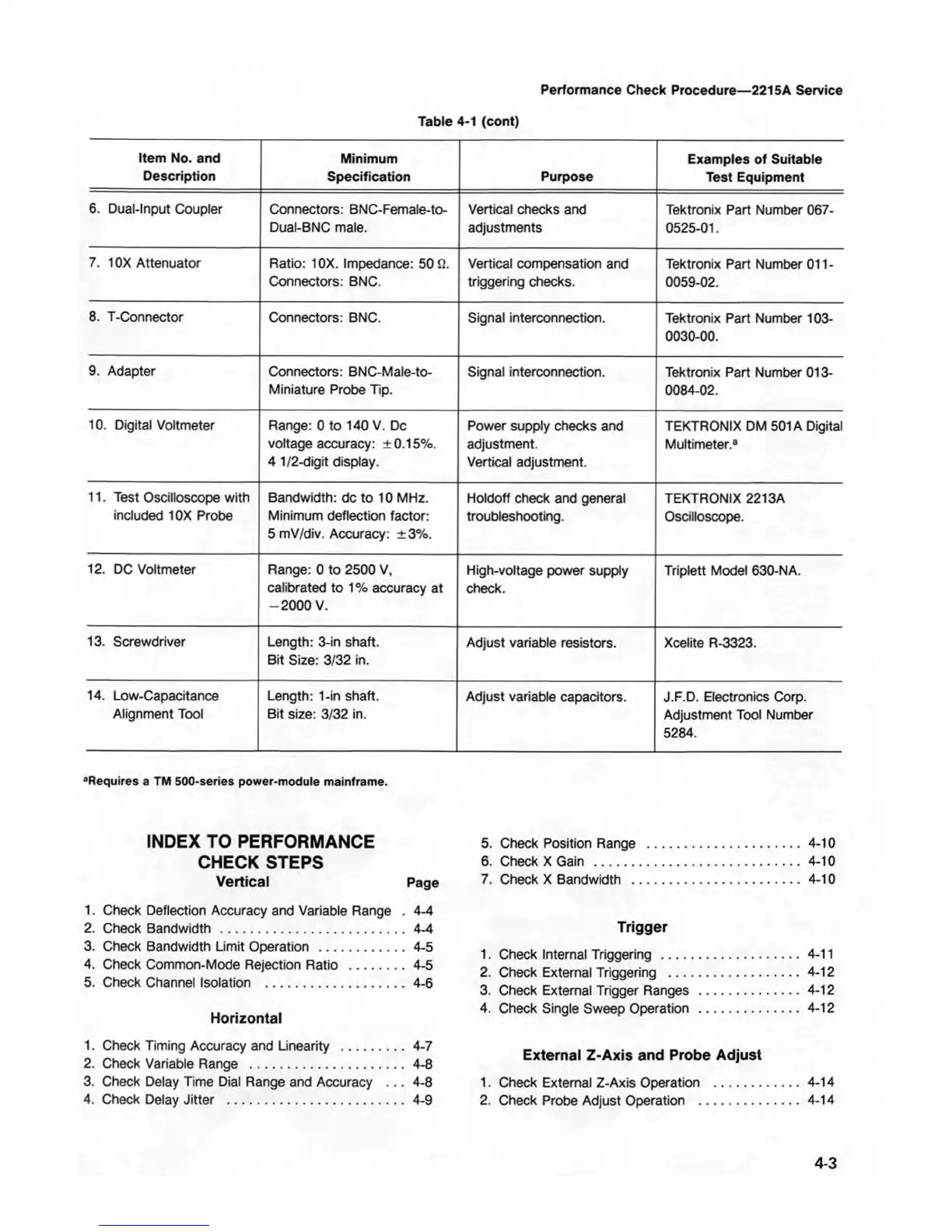
Table 4-1 (cont)
Item No. and
Description
Minimum
Specification Purpose
Examples of Suitable
Test Equipment
6. Dual-Input Coupler
Connectors: BNC-Female-to-
Dual-BNC male.
Vertical checks and
adjustments
Tektronix Part Number 067-
0525-01.
7. 10X Attenuator
Ratio: 10X. Impedance: 50 fi.
Connectors: BNC.
Vertical compensation and
triggering checks.
Tektronix Part Number 011-
0059-02.
8. T-Connector
Connectors: BNC. Signal interconnection.
Tektronix Part Number 103-
0030-00.
9. Adapter
Connectors: BNC-Male-to-
Miniature Probe Tip.
Signal interconnection.
Tektronix Part Number 013-
0084-02.
10. Digital Voltmeter
Range: 0 to 140 V. Dc
voltage accuracy: ±0.15%.
4 1/2-digit display.
Power supply checks and
adjustment.
Vertical adjustment.
TEKTRONIX DM 501A Digital
Multimeter.3
11. Test Oscilloscope with
included 10X Probe
Bandwidth: dc to 10 MHz.
Minimum deflection factor:
5 mV/div. Accuracy: ±3%.
Holdoff check and general
troubleshooting.
TEKTRONIX 2213A
Oscilloscope.
12. DC Voltmeter
Range: 0 to 2500 V,
calibrated to 1% accuracy at
-2000 V.
High-voltage power supply
check.
Triplett Model 630-NA.
13. Screwdriver
Length: 3-in shaft.
Bit Size: 3/32 in.
Adjust variable resistors.
Xcelite R-3323.
14. Low-Capacitance
Alignment Tool
Length: 1-in shaft.
Bit size: 3/32 in.
Adjust variable capacitors. J.F.D. Electronics Corp.
Adjustment Tool Number
5284.
■Requires a TM 500-series power-module mainframe.
INDEX TO PERFORMANCE
CHECK STEPS
Vertical Page
1. Check Deflection Accuracy and Variable Range . 4-4
2. Check Bandwidth .................................................. 4-4
3. Check Bandwidth Limit Operation
.......................
4-5
4. Check Common-Mode Rejection Ratio
.................
4-5
5. Check Channel Isolation ...................................... 4-6
Horizontal
1. Check Timing Accuracy and Linearity
...................
4-7
2. Check Variable Range
............................................
4-8
3. Check Delay Time Dial Range and Accuracy . .. 4-8
4. Check Delay Jitter
..................................................
4-9
5. Check Position Range
...........................................
4-10
6. Check X Gain
.........................................................
4-10
7. Check X Bandwidth
...............................................
4-10
Trigger
1. Check Internal Triggering .......................................4-11
2. Check External Triggering .....................................4-12
3. Check External Trigger Ranges
............................
4-12
4. Check Single Sweep Operation
............................
4-12
External Z-Axis and Probe Adjust
1. Check External Z-Axis Operation
.........................
4-14
2. Check Probe Adjust Operation
.............................
4-14
4-3