Performance Check Procedure—2215A Service
VERTICAL
Equipment Required (see Table 4-1):
Calibration Generator (Item 1) 50-0 BNC Termination (Item 5)
Leveled Sine-Wave Generator (Item 2)
Dual-Input Coupler (Item 6)
50-0 BNC Cable (Item 4)
10X Attenuator (Item 7)
INITIAL CONTROL SETTINGS
Vertical (Both Channels)
POSITION
Midrange
VERTICAL MODE
CH 1
BW LIMIT
On (button in)
VOLTS/DIV 2 mV
VOLTS/DIV Variable
CAL detent
INVERT Off (button out)
Input Coupling
DC
Horizontal
POSITION Midrange
HORIZONTAL MODE
A
A SEC/DIV 0.2 ms
SEC/DIV Variable CAL detent
X I0 Magnifier
Off (knob in)
A TRIGGER
VAR HOLDOFF NORM
Mode P-P AUTO
SLOPE OUT
LEVEL Midrange
A&B INT VERT MODE
A SOURCE INT
A EXT COUPLING AC
PROCEDURE STEPS
1. Check Deflection Accuracy and Variable Range
a. Connect the standard-amplitude generator output via
a 50-fi cable to the CH 1 OR X input connector.
1 VOLTS/DIV Variable control to the CAL detent and con
tinue with the 50-mV check.
c. Move the cable from the CH 1 OR X input connector to
the CH 2 OR Y input connector. Set the VERTICAL MODE
switch to CH 2.
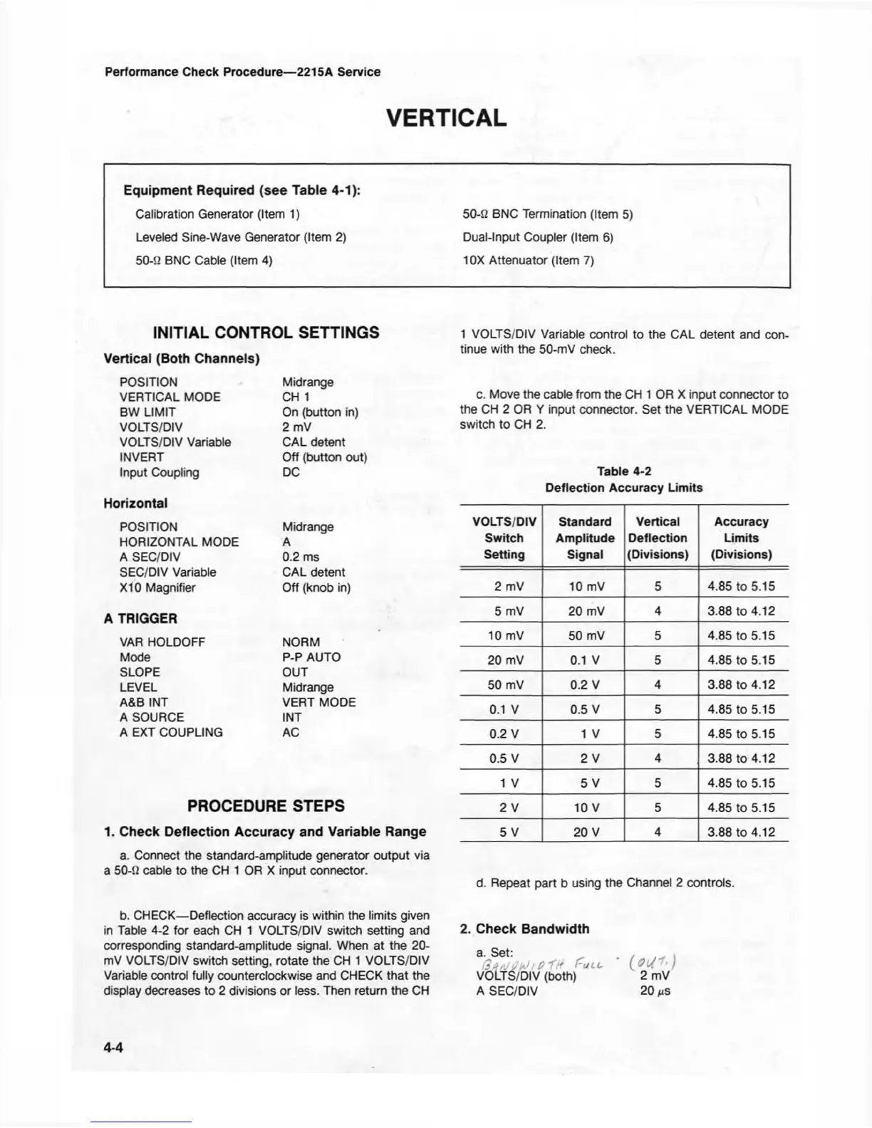
Table 4-2
Deflection Accuracy Limits
VOLTS/DIV
Standard Vertical
Accuracy
Switch Amplitude Deflection Limits
Setting
Signal
(Divisions)
(Divisions)
2 mV 10 mV 5
4.85 to 5.15
5 mV 20 mV
4
3.88 to 4.12
10 mV 50 mV
5 4.85 to 5.15
20 mV 0.1 V 5 4.85 to 5.15
50 mV 0.2 V
4
3.88 to 4.12
0.1 V
0.5 V 5 4.85 to 5.15
0.2 V 1 V
5 4.85 to 5.15
0.5 V
2 V
4
3.88 to 4.12
1 V 5 V 5 4.85 to 5.15
2 V 10 V
5
4.85 to 5.15
5 V 20 V
4
3.88 to 4.12
d. Repeat part b using the Channel 2 controls.
b. CHECK— Deflection accuracy is within the limits given
in Table 4-2 for each CH 1 VOLTS/DIV switch setting and 2. Check Bandwidth
corresponding standard-amplitude signal. When at the 20- „
mV VOLTS/DIV switch setting, rotate the CH 1 VOLTS/DIV
^ . £ ULL
*
( o J / )
Variable control fully counterclockwise and CHECK that the VOLTS/DIV (both) 2 mV
display decreases to 2 divisions or less. Then return the CH A SEC/DIV 20
i*s
4-4