Theory of Operation—2215A Service
The Alternate B Sweep circuitry controls the Alt and
B Horizontal mode displays and includes the B Miller Sweep
Generator and B Sweep Logic circuitry. In addition to pro
viding the B Sweep sawtooth waveform, signals are gener
ated which control the display switching between the A and
B displays.
The intensity levels of both the A and B Sweeps are set
by the front-panel A and B INTENSITY controls. These con
trols, along with signals from the A and B Sweep Logic
circuits, determine the drive level to the Z-Axis Amplifier.
The Z-Axis drive from both the A Sweep Logic circuit and
the Alternate B Sweep circuit is applied to the Z-Axis Ampli
fier. The output signal from the Z-Axis Amplifier circuit sets
the crt intensity. When using Chop Vertical mode, a blanking
signal from the Chop Oscillator circuit blanks the crt display
while switching between the vertical channels.
The Dc Restorer circuit applies the output voltage of the
Z-Axis Amplifier between the cathode and grid of the crt.
High dc potentials on these elements prohibit direct coupling
to the crt.
The Power Supply provides the necessary operating
voltages for the instrument. Operating potentials are ob
tained from a circuit composed of the Preregulator, Inverter
and Transformer, and Rectifiers and Filters. The
Preregulator produces approximately +43 V dc from the ac
power line which is used to drive the 20 kHz Inverter stage.
The transformer secondary windings provide various ac lev
els that are rectified and filtered to produce the operating
voltages. A high-voltage multiplier circuit produces the ac
celerating, focus, and cathode potentials required by the crt.
A front-panel PROBE ADJUST output is provided for use
in adjusting probe compensation. The voltage at the
PROBE ADJUST connector is a negative-going square
wave that has a peak-to-peak amplitude of approximately
0.5 V and a repetition rate of approximately 1 kHz.
DETAILED CIRCUIT DESCRIPTION
VERTICAL ATTENUATORS
The Channel 1 and Channel 2 Attenuator circuits, shown
on Diagram 1, are identical with the exception of the addi
tional Invert circuitry in the Channel 2 Paraphase Amplifier.
Therefore, only the Channel 1 Attenuator will be described
and the Invert circuitry of Channel 2 will be discussed
separately.
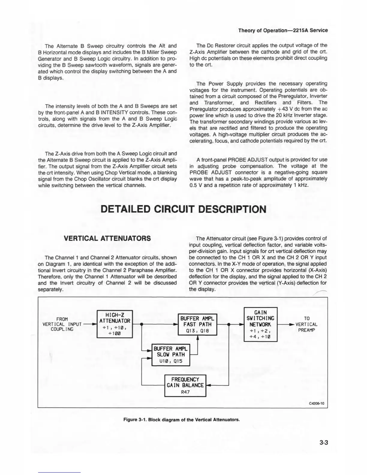
The Attenuator circuit (see Figure 3-1) provides control of
input coupling, vertical deflection factor, and variable volts-
per-division gain. Input signals for crt vertical deflection may
be connected to the CH 1 OR X and the CH 2 OR Y input
connectors. In the X-Y mode of operation, the signal applied
to the CH 1 OR X connector provides horizontal (X-Axis)
deflection for the display, and the signal applied to the CH 2
OR Y connector provides the vertical (Y-Axis) deflection for
the display.
3-3
Figure 3-1. Block diagram of the Vertical Attenuators.