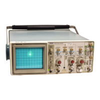
2215A Service
TEST WAVEFORM AND VOLTAGE SETUPS
WAVEFORM MEASUREMENTS
On the left-hand pages preceding the schematic dia
grams are test waveform illustrations that are intended to
aid in troubleshooting the instrument. To test the instrument
for these waveforms, make the initial control settings as
follows:
Vertical (Both Channels)
POSITION Midrange
VERTICAL MODE CH 1
BW LIMIT Off (button out)
VOLTS/DIV 10 mV
VOLTS/DIV Variable
CAL detent
INVERT
Off (button out)
Input Coupling GND
Horizontal
POSITION Midrange
HORIZONTAL MODE
A
A and B SEC/DIV
0.5 ms
SEC/DIV Variable CAL detent
X I0 Magnifier
Off (knob in)
B DELAY TIME POSITION
5.0
B TRIGGER
LEVEL Fully clockwise
SLOPE
OUT
A TRIGGER
VAR HOLDOFF
Minimum (fully ccw)
Mode P-P AUTO
LEVEL
Midrange
A&B INT
VERT MODE
A SOURCE
INT
Changes to the control settings for specific waveforms
are noted at the beginning of each set of waveforms. Input
signals and hookups required are also indicated, if needed,
for each set of waveforms.
DC VOLTAGE MEASUREMENTS
Typical voltage measurements, located on the schematic
diagram, were obtained with the instrument operating under
the conditions specified in the Waveforms Measurements
setup. Control-setting changes required for specific voltages
are indicated on each waveforms page. Measurments are
referenced to chassis ground with the exception of the
Preregulator and Inverter voltages on Diagram 7. These
voltages are referenced as indicated on the schematic
diagram.
RECOMMENDED TEST EQUIPMENT
Test equipment in Table 4-1 in the "Performance Check
Procedure”, Section 4 of this manual, meets the required
specifications for testing this instrument.

 Loading...