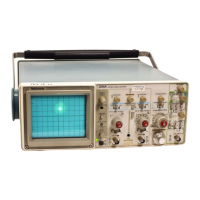
Adjustment Procedure—2215A Service
b. Position the trace on the center horizontal graticule
line using the Channel 2 POSITION control.
c. Set the CH 2 VOLTS/DIV switch to 2 mV.
d. ADJUST—Ch 2 2/5 mV Dc Bal (R83) to set the trace
on the center horizontal graticule line.
e. Repeat parts a through d until there is no trace shift
when changing the CH 2 VOLTS/DIV switch from 5 mV to
2 mV.
f. Set the VERTICAL MODE switch to CH 1.
g. Repeat parts a through e for Channel 1, adjusting Ch 1
2/5 mV Dc Bal (R33) in part d.
3. Adjust Channel 1 Variable Balance (R25)
a. Set both VOLTS/DIV switches to 10 mV.
b. Rotate the CH 1 VOLTS/DIV Variable control fully
counterclockwise.
c. Position the trace on the center horizontal graticule line
using the Channel 1 POSITION control.
d. Rotate the CH 1 VOLTS/DIV Variable control clock
wise to the CAL detent.
e. ADJUST—Ch 1 Var Bal (R25) to set the trace to the
center horizontal graticule line.
f. Repeat parts b through e until there is no trace shift
between the fully clockwise and the fully counterclockwise
positions of the CH 1 VOLTS/DIV Variable control.
g. Return the CH 1 VOLTS/DIV Variable control to the
CAL detent.
4. Adjust Channel 2 Invert Balance (R75)
a. Set the VERTICAL MODE switch to CH 2.
b. Position the trace on the center horizontal graticule
line using the Channel 2 POSITION control.
c. Set the INVERT button to On (button in).
d. ADJUST—Ch 2 Invert Bal (R75) to set the trace to the
center horizontal graticule line.
e. Set the INVERT button to Off (button out).
f. Repeat parts b through e until there is no trace shift
when switching the INVERT button between the On and Off
positions.
g. Repeat Steps 2 and 3 for Channel 1 until no further
improvement is noted.
h. Repeat Steps 2 and 4 for Channel 2 until no further
improvement is noted.
5. Adjust MF/LF Compensation and Gain Balance
(C53, R97, C3, and R47).
a. Set:
VERTICAL MODE CH 2
VOLTS/DIV (both) 10 mV
Input Coupling (both) DC
A SEC/DIV 20
ns
b. Connect the high-amplitude square wave output via a
50-0 cable, a 10X attenuator, and a 50-0 termination to the
CH 2 OR Y input connector.
c. Set the generator to produce a 10-kHz, 5-division
display.
d. Set the top of the display on the center horizontal
graticule line using the Channel 2 POSITION control.
e. ADJUST—Ch 2 MF/LF Comp (C53) and Ch 2 MF/LF
Gain Bal (R97) for the best front corner and flat top.
f. Move the cable from the CH 2 OR Y input connector to
the CH 1 OR X input connector. Set the VERTICAL MODE
switch to CH 1.
g. Set the top of the display on the center horizontal
graticule line using the Channel 1 POSITION control.
5-7

 Loading...