4-17
n. Select VERTICAL MODE and set ADD on and
CH 2 oft.
m. Repeat parts b through k to check CH
2
triggers,
using CH
2
control settings and input connector. Skip
parts f, hand i and check only for DC trigger coupling in
part g if the DC trigger sensitivity is NOT near the
specified limits; otherwise, check as for CH
1.
I.
Select VERTICAL MODE and set CH 1 off and
CH 2 on.
k. Repeat parts
d
through
j
(skip part
f)
to check A
Triggers for each test frequency setting in Table 4-3.
Change generators (as specified in part a) as needed to
obtain the test frequency required. Return the TRIGGER
COUPLING menu to DC when completed.
j. Set the generator output to the next Test Frequency
in Table 4-3.
i. Change the generator output amplitude as necessary
and repeat parts g through h for any Trigger Coupling set-
ting specifying a different Minimum Display Level for
triggering other that the initial setting for that row. (For
example, NOISE, HF, and LF settings usually-but not
always-require different amplitudes than the initial
setting.)
h. CHECK-For no stable trigger (display free-runs) for
any TRIGGER COUPLING setting in Table 4-3 specifying
footnote b, "Not Triggered at specified amplitude."
g. CHECK-For a stable,-triggered display on both +
and - slopes for all TRIGGER COUPLING settings that
are specified at the present Test Frequency.
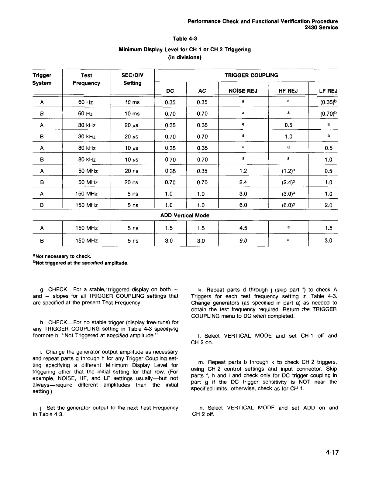
aNot necessary to check.
bNot triggered at the specified amplitude.
A 150 MHz 5 ns
1.5 1.5 4.5
a
1.5
B 150 MHz 5 ns
3.0 3.0 9.0
a
3.0
ADD Vertical Mode
Trigger Test SEC/DIV TRIGGER COUPLING
System
Frequency Setting
DC AC NOISE REJ HF REJ LF REJ
A 60 Hz 10 ms
0.35
0.35
a a
(0.35)b
B 60 Hz 10 ms 0.70 0.70
a a
(0.70)b
A 30 kHz
20
ILS
0.35
0.35
a
0.5
a
B 30 kHz
20
ILS
0.70 0.70
a
1.0
a
A 80 kHz
10
ILS
0.35 0.35
a a
0.5
B 80 kHz
10
ILS
0.70 0.70
a a
1.0
A 50 MHz 20 ns
0.35
0.35 1.2
(1.2)b
0.5
B
50 MHz
20 ns 0.70 0.70 2.4
(2.4)b
1.0
A 150 MHz 5 ns
1.0 1.0 3.0
(3.0)b
1.0
B
150 MHz 5 ns 1.0 1.0 6.0
(6.0)b
2.0
Table 4-3
Minimum Display Level for CH
1
or CH
2
Triggering
(in divisions)
Performance Check and Functional Verification Procedure
2430 Service
 Loading...


