When checking semiconductors, observe the static-
sensitivity precautions located at the beginning of
this section.
To avoid electric shock, always disconnect the
instrument from the ac power source before remov-
ing or replacing components.
11. Check Individual Components
I
WARNING
I
Voltages and waveforms indicated on the schematic
diagrams are not absolute and may vary slightly
between instruments. To establish operating condi-
tions similar to those used to obtain these readings,
set up the Test scope and the 2430 under test as
indicated near the waveform illustrations for a
schematic diagram.
NOTE
10. Check Voltages and Waveforms
Often the defective component can be located by
checking circuit voltages or waveforms. Typical voltages
are listed on the schematic diagrams. Waveforms indicated
on the schematic diagrams by hexagonally outlined
numbers are shown adjacent to the diagrams. Waveform
test points are shown on the circuit board illustrations.
9. Check Circuit Board Interconnections
After the trouble has been isolated to a particular cir-
cuit, again check for loose or broken connections, improp-
erly seated semiconductors, and heat-damaged
components.
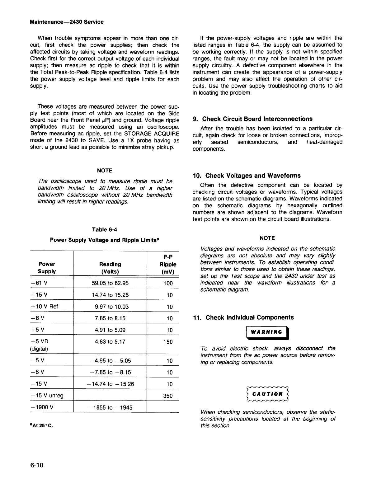
If the power-supply voltages and ripple are within the
listed ranges in Table 6-4, the supply can be assumed to
be working correctly. If the supply is not within specified
ranges, the fault mayor may not be located in the power
supply circuitry. A defective component elsewhere in the
instrument can create the appearance of a power-supply
problem and may also affect the operation of other cir-
cuits. Use the power supply troubleshooting charts to aid
in locating the problem.
6-10
POp
Power
Reading
Ripple
Supply
(Volts)
(mV)
+61 V
59.05 to 62.95
100
+15 V 14.74 to 15.26
10
+10 V Ref
9.97 to 10.03
10
+8V 7.85 to 8.15
10
+5V 4.91 to 5.09
10
+5 VO 4.83 to 5.17
150
(digital)
-5V
-4.95 to -5.05
10
-8V
-7.85 to -8.15
10
-15 V
-14.74 to -15.26
10
-15 V unreg
350
-1900 V
- 1855 to - 1945
Table 6-4
Power Supply Voltage and Ripple Limits
8
The oscilloscope used to measure ripple must be
bandwidth limited to 20 MHz. Use of a higher
bandwidth oscilloscope without 20 MHz bandwidth
limiting will result in higher readings.
NOTE
These voltages are measured between the power sup-
ply test points (most of which are located on the Side
Board near the Front Panel /oLP)and ground. Voltage ripple
amplitudes must be measured using an oscilloscope.
Before measuring ac ripple, set the STORAGE ACQUIRE
mode of the 2430 to SAVE. Use a 1
X
probe having as
short a ground lead as possible to minimize stray pickup.
When trouble symptoms appear in more than one cir-
cuit, first check the power supplies; then check the
affected circuits by taking voltage and waveform readings.
Check first for the correct output voltage of each individual
supply; then measure ac ripple to check that it is within
the Total Peak-to-Peak Ripple specification. Table 6-4 lists
the power supply voltage level and ripple limits for each
supply.
Maintenance-2430 Service