In external clock mode, the differential EXTCK and
EXTCK (external clock) signals to the Phase Clock circuit
replace the normal master-clock (MCLK) signal and allows
the B trigger events to be used as the events delay
source.
The Time Base Controllerthen starts moving digitized
samples to the Acquisition Memory and, when finished,
tells the System MPthat the acquisitionis done. The Sys-
tem MPmay then restart the whole process again for the
next acquisitionby writing appropriate data to the various
trigger registers.
6. Time Base Controller U670 (diagram8) counts the
post-trigger samples as they are acquired. When the
required count is reached to complete the acquisition, it
resets EPTHOto LO and further triggers from the Trigger
Logic Array are preventedfrom beinggenerated.
5. In this example, when the internal Delay count
reaches 0, a RTRIG (record trigger) is generated for B
RUNS AFTER. RTRIGis the"record trigger" point on the
displayedwaveform. If the mode were B TRIG AFTER,the
Trigger Logic Array would begin watching for a B Trigger
to occur on the DTG and DTG input pins (Delay Trigger
Gate).
4. The defined delay count is decrementedto zero by
the DELCLK (delay clock) signal on pin 67 from Phase
Clock Array U470. If the mode were A Delayed by B
Events, the B Trigger events would be used to decrement
the delaycounter.
3. With EPTHO HI, the Trigger Logic Array watches
MTG and MTG (main trigger gate)for an A trigger event to
start the delay counter. When a trigger occurs, JTRIG
(jitter trigger)is generated,starting the jitter-correction cir-
cuits (via the RAMP and RAMP signals).
2. The Trigger Logic Array watches for EPTHO at
pin 28 to go HI; signaling that the defined number of
pretriggerpoints have beensampled.
1. The System ~P loads the"delay count" and "con-
trol mode" registers, then starts the acquisition (indicated
by setting RSTACO HI at TP370).
Operation of the Trigger Logic Array is very sequential
in the way it functions in the various trigger modes. An
example is illustratedin the sequence of events for B
RUNS AFTERtrigger mode.
3-50
After the control data byte is loaded and the acquisition
is restarted, Trigger Logic Array U370 waits for EPTHO
(endof pretriggerholdoff)to go HI at pin 28, indicatingthat
the acquisition system has sampled the"pretrigger"
points and is ready to complete the acquisition. With
EPTHOset HI, the trigger logic beginswatching the trigger
source (as defined by the control data byte), waiting for a
trigger event to occur.
As previously mentioned, U370 provides final trigger-
mode and source selection, dependent on data written
from the System~P to a control register within U370 at
address 6082h. The mode control data byte loaded from
the MO-M7input bus is built by the System ~P and applied
to the MO-M7(mode)inputs from serial-inputregister U270
(diagram5) via the GADO-GAD7bus lines. The data byte
defines the A Trigger source, B Trigger source, Record
Trigger source, Jitter Trigger source, and whether a single
event or multiple events are needed to produce a trigger.
Bit definitionis shownin Figure3-6.
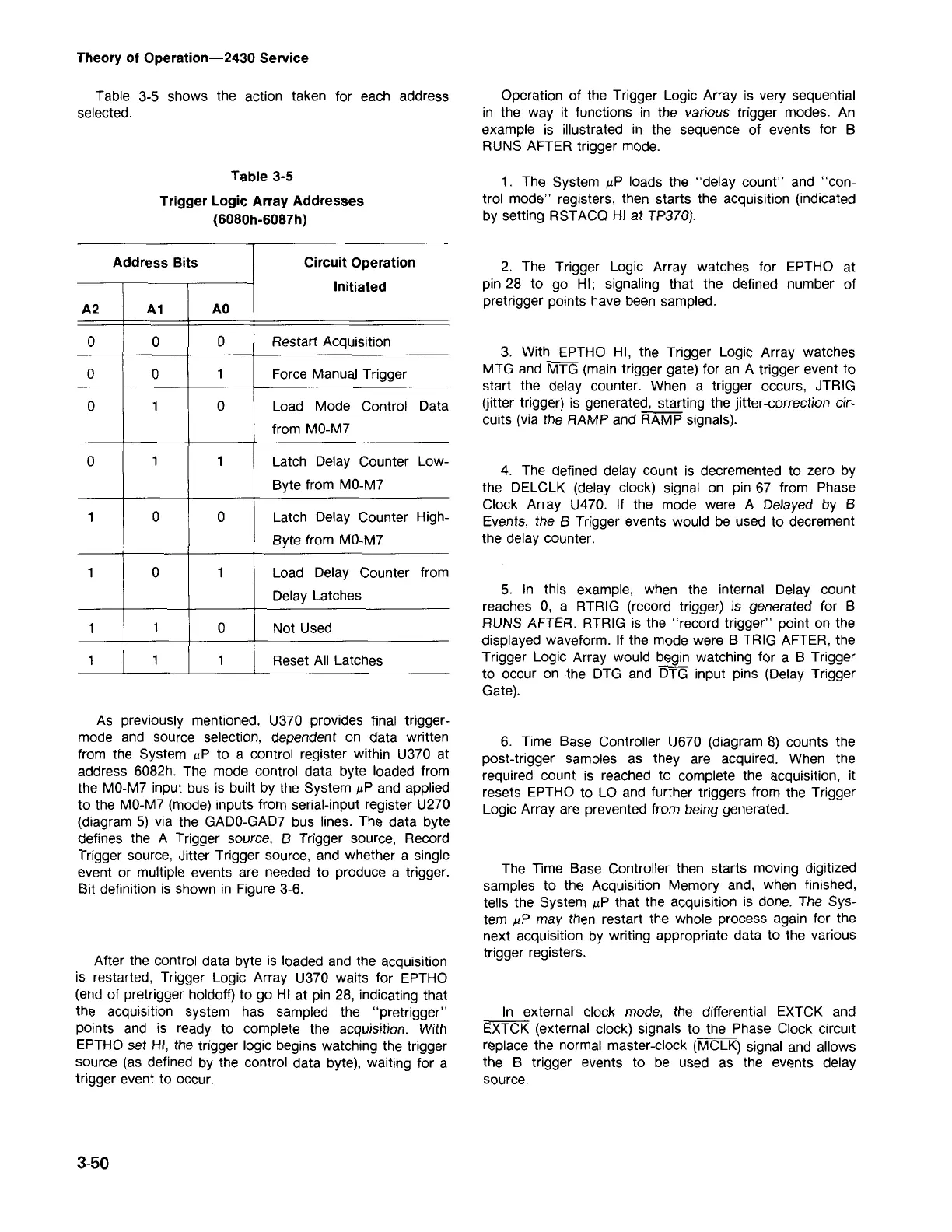
Address Bits Circuit Operation
Initiated
A2 A1
AO
0
0
0
Restart Acquisition
0
0
1
ForceManualTrigger
0
1
0
Load Mode Control Data
from MO-M7
0
1 1
Latch Delay Counter Low-
Byte from MO-M7
1
0
0 Latch Delay Counter High-
Byte from MO-M7
1
0
1
Load Delay Counter from
DelayLatches
1
1
0
Not Used
1
1 1
Reset All Latches
Table 3-5
Trigger Logic Array Addresses
(6080h-6087h)
Table 3-5 shows the action taken for each address
selected.
Theory of Operation-2430 Service