TM 11-6325-2735-14-1
Simplified Block Diagram
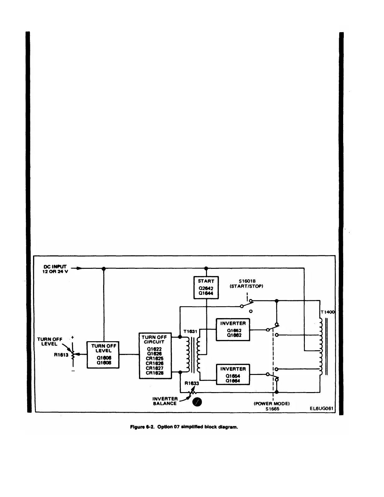
See Figure 6-2. The dc source is applied to the turn-off
level circuit, the start circuit and the primary of T1400. If
he dc source is above the level set by Turn-Off Level
adjustment R1613, the turn-off circuit does not operate.
The start circuit provides a large current surge through
1631 secondary to the bases of Q1652, Q1662, Q1654
and Q1664. This starts the inverter.
The turn-off circuit is activated in two ways. In 24 V
operation, Q1622 is turned on by the source voltage
dropping below 22 V. In 12 V mode of operation, Q1626 is
turned on by the accidental application of 24 V dc.
Turn-Off Level Circuit
For the following description, refer to figure 6-3.
The voltage reference for the base of Q1606 is set by
R1604, VR1604 and VR1605 for about 9.1 V. This es-
tablishes the junction of R1607 and the emitters of Q1606
and Q1608 at about 9.7 V. C1605 helps to hold the 9.1 V
level, preventing inverter transients from activating the
turn-off circuit and prevents Q1608 from turning on when
the inverter is started. This allows the power source time to
recover after providing the initial-start surge.
Source voltages higher than 22 V dc cause increased
current through R1607, Q1606 and R1609. Q1608 is kept
cut off by the increased voltage across R1609 and the
resulting change across divider R1611-R1613-R1614. This
permits no current through R1617. Since R1617 furnishes
bias to Q1622, the transistor is cut off. This permits the
collector of Q1622 and the rest of the turn-off circuit to rise
to a voltage determined by the inverter circuit and the dc
source voltage. The collector of Q1622 may be about 24 V
(with respect to minus dc) with a 12 V dc source and about
36 V with a 24 V dc source.
If the dc source voltage drops to less than 22 V, the
current through divider R1609, R1611, R1613 and R1614 is
decreased. Q1608 conducts, taking current from Q1606,
and causing less drop across R1609. This makes Q1608
conduct more and Q1606 is cut off. Current flow through
R1617 turns Q1622 on. Q1622 saturates, dropping its
collector voltage to about 0.2 V. R1618 limits the max-
imum base current of Q1622.
During 12 V dc operation, there is no current flow
through VR1604 and VR1605, since their series rating,
about 18 volts, exceeds the applied voltage. The base
current of Q1606, through R1605, turns Q1606 on enough
to take all the current through R1607, which causes Q1608
to be cut off.
6-2.2 Change 1
 Loading...


