Operating Basic
s
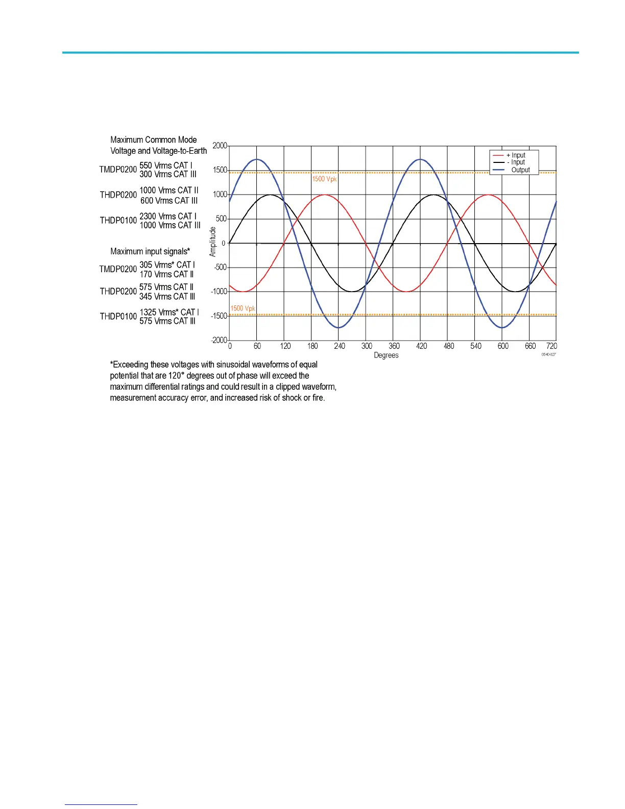
Example 2. Next, assume that the same waveforms from the previous example are 120° out of phase w ith each other.
(See Figure 4.)
This phase relationship yields a maximum differential of 1.732 times the individual signal inputs, or 1732 V
pk
.
Although this is a lower potential between the inputs than in example 1, it exceeds the differential v oltage ratings of the
THDP0200 and TMDP0200 probes, so you must use the THDP0100 probe.
Figure 4: Measuring two equal-amplitude waveforms that are 120 degrees out of phase
Example 3. Your task is to measure two AC waveforms of the same phase, each with an amplitude of 300 V. However,
one waveform is centered on ground (– input), and the other is centered on an offset of 400 VDC (+ input). The common
mode voltage is the 300 V
rms
, but the maximum voltage-to-earth (the common mode voltage plus the signal waveform)
must also be taken into account for both inputs. The voltage-to-earth is 300 V
rms
on the (– input), but on the (+ input),
the voltage-to-earth is 700 V
rms
(the 300 VAC
rms
plus the 400 VDC
rms
). Thus the (+ input) exceeds the maximum input
voltage-to-earth rating of the THDP0200 probe, so it cannot be used for taking this measurement. In this case, you m ust use
either the T MDP0200 or THDP0100 probe.
THDP0100/0200 & TMDP 0200 High Voltage Differential Probes Instruction Manual 24