Operating Basic
s
Overrange Detection
Differential voltage outside the operating range will o verdrive the circuitry of the probe and distort the output signal. When
this differential overrange occurs, the probe detects the condition and lights the overrange indicator. With the Audible
Overrange ON, the probe will also emit an audible alarm.
WARNING. The Overrange indicator does not detect an overrange condition of common-mode voltages or voltage-to-earth
potential at the probe inputs. The Overrange indicator only detects differentially between the + and – inputs (not relative to
ground). D o not exceed the Common-Mode Voltage or Input Voltage-to-Earth ratings of the probe when taking measurements.
If you are not sure, first take a single-ended measurement of each point that you are intending to measure differentially.
Take a single-ended measurement by tying one input lead to ground (the – input) and then connecting the o ther lead (the +
input) to the points of interest, one at a time.
Common-Mode Rejection
The common-mode rejection ratio (CMRR) is the specified ability of a probe to reject signals that are common to both inputs.
More precisely, CMRR is the ratio of the differential gain to the common-mode gain. The higher the ratio, the greater the
ability o
f probe to reject common-mode signals.
Common mo
de rejection decreases as the input frequency increases. For example, if you apply a 60 Hz line voltage of
500 V
p-p
to both input leads of the probe, the probe rejects the signal by 80 dB (typical) and the signal appears as only a
50 mV
p-p
signal on the oscilloscope screen.
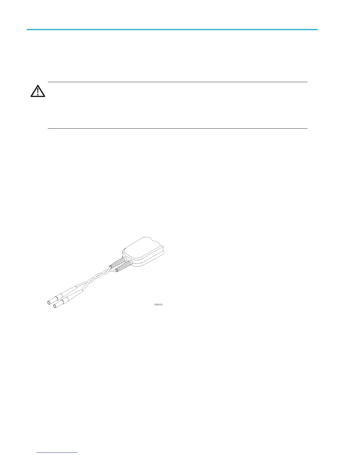
Twistin
g the Input Leads
Twisting the input leads helps to canc el noise from high-EMI environments that is induced into the input leads.
Probe Loading
When you touch your probe tip to a circuit element, you are introducing a new resistance, capacitance, and inductance into
th
e c ircuit. Frequency and impedance of the source determine how much the probe loads the circuit you are measuring. As
the frequency of the source starts to increase beyond 1 kHz, the input impedance of the probe begins to decrease.
The lower the impedance o f the probe relative to that of the source, the more the probe loads the circuit under test. For a
graph of frequency versus input impedance, refer to the Specifi cations section. As the graph shows, the probes have virtually
no
loading effect on sources with relatively low impedance and low frequency.
25 THDP0100/0200 & TMDP0200 High Voltage Differential Probes Instruction Manual