Adjustments
Gain Accuracy
The equipment settings for this test differ between probes. Refer to the table for specific settings for the probe that you
are testing. (See Table 16.)
WARNING. Dangerous voltages will be present on the calibration generator output terminals and connection cables. Always
verify that the generator is in the standby mode before y ou make any connections to the generator.
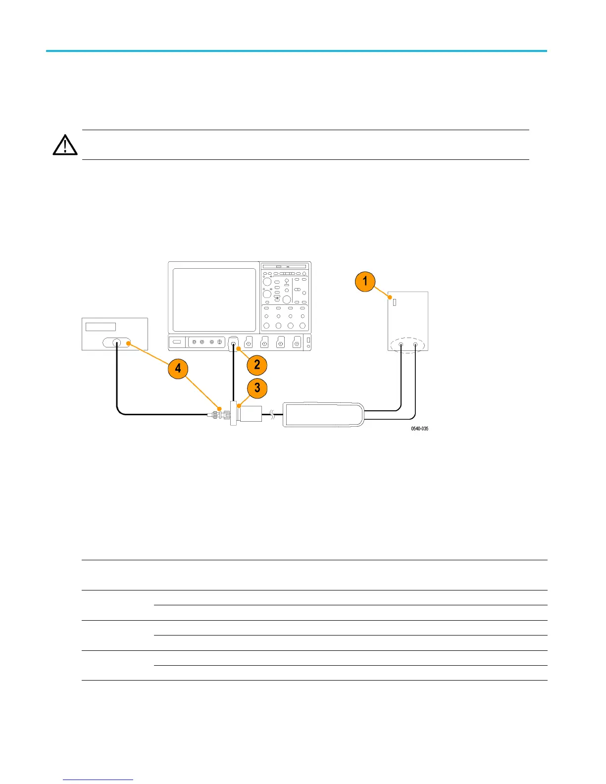
1. Verify that the generator output is off.
2. Connect the probe calibration fixture to any channel (1–4) on the oscilloscope.
3. Connect the probe output to the probe calibration fixture.
4. Connect the output of the probe calibration fixture to the inputs of the DMM, using coax cables and adapters.
5. Set the DMM to AC volts.
6. Connect the probe inputs to the front outputs of the generator, using adapters if necessary.
7. Set the probe attenuation to the lower (most sensitive) range for the probe that you are adjusting.
8. Set the generator square wave output frequency and RMS voltage (main display) to the values shown in the table for the
probe that you are adjusting. (See Table 16.)
Table 16: Adjust gain accuracy equipment settings
Probe Generator square wave output Probe output voltage
Model Range Voltage (rms) Frequency Expected (rms) Measured (rms)
600 V 75 V 100 Hz 750 mV ±15 mVTHDP0100
6000 V 75 V 100 Hz 75 mV ±1.5 mV
150 V 25 V 100 Hz 500 mV ±10 mVTHDP0200
1500 V 75 V 100 Hz 150 mV ±3 mV
75 V 20 V 100 Hz 800 mV ±16 mVTMDP0200
750 V 60 V 100 Hz 240 mV ±4.8 mV
45 THDP0100/0200 & TMDP0200 High Voltage Differential Probes Instruction Manual
 Loading...


