Portable Mainframe Removal and Installation Procedures
TLA7000 Series Mainframe Technical Reference Manual
11
NOTE. When installing the four jack screws, tighten them to 4 in-lbs.
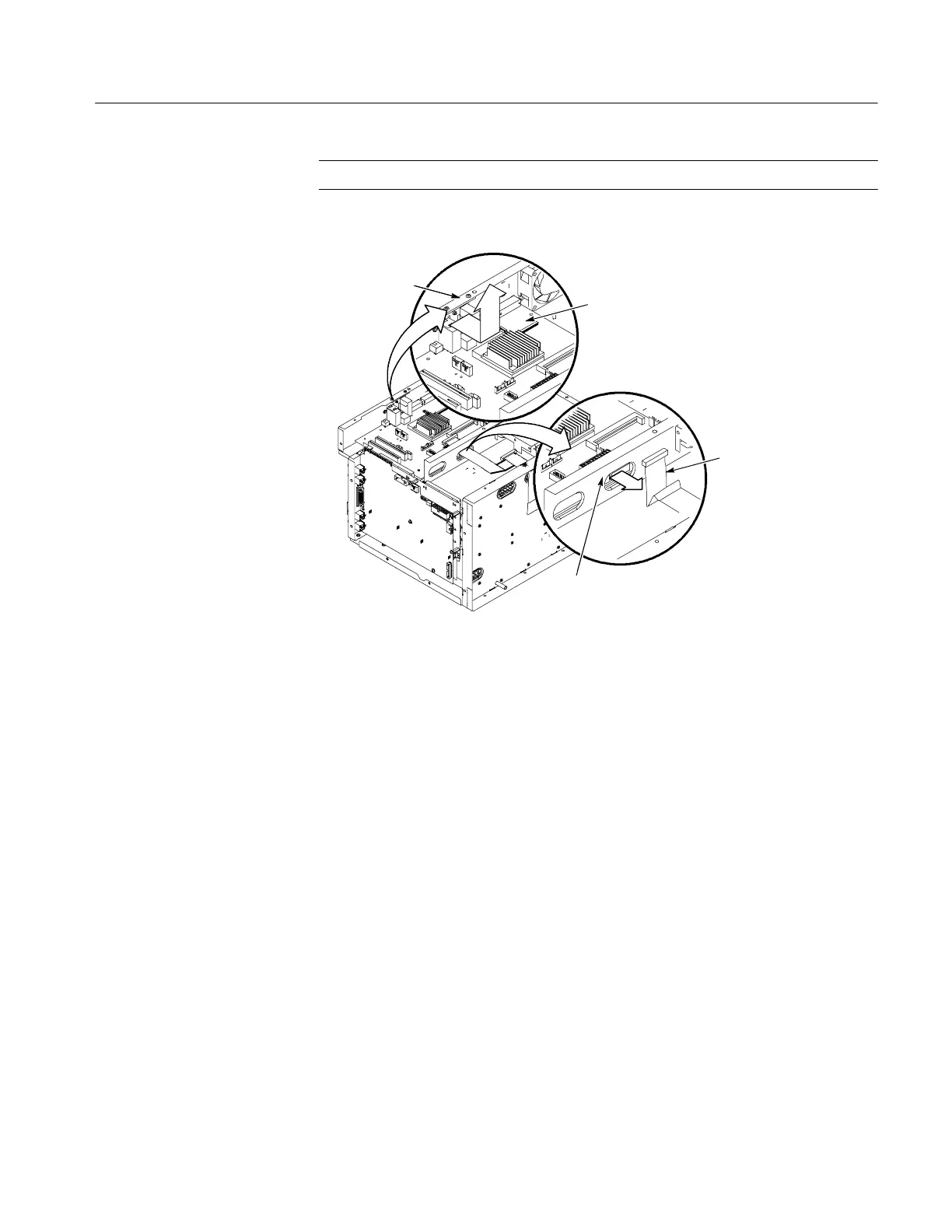
Motherboard
USB grounding
bracket
Chassis bracket
DVD cable
Figure 6: Removing the m otherboard
Interface Board
Complete the following steps to remove the interface board. Refer to Figure 24
on page 45 for the detailed exploded view drawings. Installation procedures are
the reverse of the removal procedures.
1. Remove the instrument covers. (See Instrument Covers on page 6.)
2. Remove the top EMI cover. (Refer to Figure 22 on page 41.)
3. Remove the hardware from the I/O bracket -- four BNC nuts, two jack
screws, and two chassis screws. (Refer to Figure 7 on page 12)
4. Gently pull out the I/O bracket.
5. Disconnect the cables from the interface board and move them out of the
way.
6. Remove the five screws securing the interface board to the chassis.
To install the interface board, watch the ground fingers on top left. (Gently bend
the board down while pushing it into place.)
 Loading...


