Application Examples
NOTE. Most v
ideo systems u se 75 ohm cabling. The oscilloscope inputs do not
properly terminate low impedance cabling. To avoid amplitude inaccuracy
from improper loading a nd reflections, place a 75 ohm feedthrough terminator
(Tektronix part number 011-0055-02 or equivalent) between the 75 ohm coaxial
cable from the signal source and the oscilloscope BNC input.
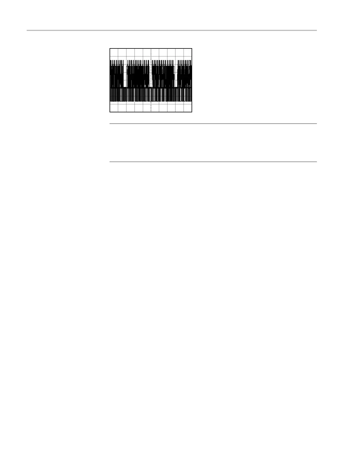
Trigger
ingonVideoFields
Automat
ic. To trigger on the video fields, follow these steps:
1. Push the AutoSet . When Autoset is complete, the oscilloscope displays the
video s
ignal with sync on All Fields.
The oscilloscope sets the Standard option when you use the Autoset function.
2. Push the Odd Field or Even Field option s from the Autoset Menu to sync
on odd or even fields only.
Manual. An alternative method requires more steps, but may be necessary
depending on the video signal. To use the manual method, follow these steps:
1. Push the channel 1 .
2. Pus
h Coupling ► AC.
3. Push the Trig Menu to see the Trigger Menu.
4. Push the top option and select Video.
5. Push Source ► CH1.
6. Push the Sync option and select All Fields, Odd Field,orEven Field.
7. Push Standard ► NTSC.
8. Turn the horizontal Scale knob to see a complete field across the screen.
9. Turn the vertical Scale knob to ensure that the entire video signal is visible
on the screen.
56 TPS2000B Series Digital Oscilloscope User Manual