Application Exa
mple
For input and reference combinations with more complex relationships, multiple circles are displayed to indicate all the
possible inter
pretations of the timing offset, with the one that is closest to zero shown with emphasis. The numerical
readouts will correspond to the timing indicator circle with the emphasis.
The Relative to: box indicates the chosen zero point for the timing display. The default is Rear Panel. In this mode,
the offset is zero when the input and reference are at the same timing at the rear panel of your instrument. The other
choice is Save
d Offset. In this mode, you can save the timing from one signal and then display the timing relative to
that saved offset.
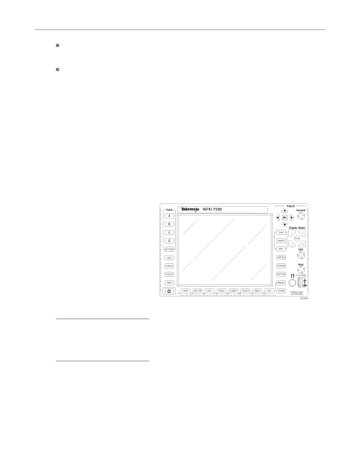
To Use the Timing Display to Time a Signal to a Reference.
1. Select a til
e in which to time the active
input.
2. Apply the input signal to be timed to the
appropriate input, terminate it properly
and select
it.
3. Apply the h
ouse reference signal to the
external reference input, terminating it
properly.
4. Press the EXT REF button to select
External
Reference mode.
5. Press th
e MEAS button to select the
Timing display for the tile selected in
step 1.
6. If only one circle is displayed, adjust
the tim
ing offset of the black generator
to match the timing to the external
reference. A djust for a perfect
coinci
dence of the circle around the
reference target (circle turns green at
coincidence) and null values of the
verti
cal and horizontal timing readouts.
7. If mul
tiple circles are displayed, the
timing is complex, and you must choose
the one you want. The measurement that
is cl
osest to zero offset is displayed with
emphasis and appears in the readouts.
NOTE. See Timing Displays for Simple
Ver
sus Complex Timing in the User Technical
Reference on the User Documentation CD
that came with your instrument for more
inf
ormation about complex timing displays
and their elements.
8. Re
peat step 6 or 7 for any other signals.
Waveform Monitors Quick Start User Manual 133
 Loading...


