10 CA60Plus control panel Installation manual
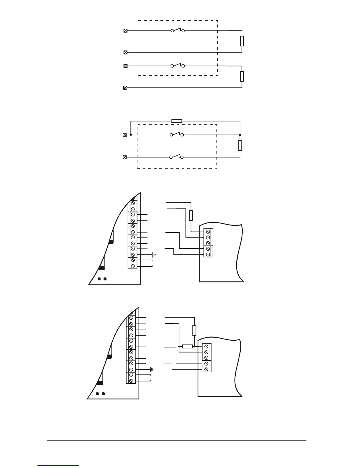
Fig. 9 Connecting a key-switch and a fire detector with relay in the base
to a CA60Plus control panel
Connecting keyswitch with two balancing resistors
1k
NC
NC
1k
ZONE x
COM
Key-switch
Must be normally closed.
Tamper switch of the key-switch.
NC
Key-switch
Must be normally closed.
NC
Tamper switch of the key-switch.
1k
1k
ZONE x
TAMPER
ZONE
COM
COM
Connecting key-switch with one balancing resistor
Connecting a fire detector with a relay in the base
in scheme with two balancing resistors
F2
B
AC
+AUX
-AUX
+PGM
PGM1
PGM2
PGM3
SIREN
Z2
COM
+12 V
GND
NO
CA60Plus
Fire
detector
base
NC
COM
1k
1k
The programmable output
must be programmed
as Fire Reset and the active
status must be +12 VDC.
Connecting a fire detector with a relay in the base
in scheme with one balancing resistor
F2
B
AC
+AUX
-AUX
+PGM
PGM1
PGM2
PGM3
SIREN
Z2
COM
+12 V
GND
NO
CA60Plus
Fire
detector
base
NC
COM
1k
The programmable output
must be programmed
as Fire Reset and the active
status must be +12 VDC.