6 CA60Plus control panel Installation manual
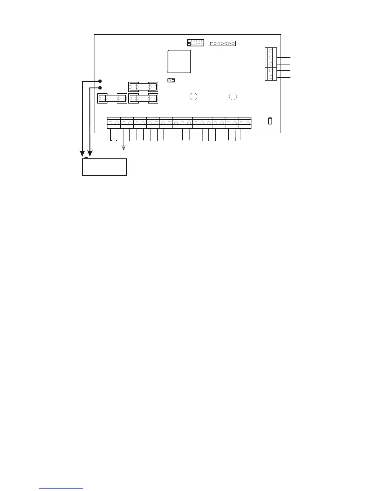
3. CA60Plus control panel inputs and outputs
• AC - power supply from 17 V/24 V A mains transformer
• Earth – conductor to “EARTH”
• +AUX and -AUX - 13 V DC power supply to sensors consuming up to 1 А
• +PGM - 13 V DC power supply to additional devices consuming up to 1 А
• PGM1, PGM2 and PGM3 – programmable outputs
• SIREN – siren programmable outputs
• Z2, Z3, Z4, Z5 and Z6 – zone inputs; ( Z1 zone is at the keyboard)
• COM – total mass of the zones
• А and В – connects the telephone line
• А1 and В1 – connects the telephone device
• RED and BLACK – keyboard power supply
• GREEN and YELLOW – interface between the panel and the keyboard
• F1 - 2 А battery fuse
• F2 - 1 А fuse for powering sensors, programmable outputs and keyboards
• F3 - additional device 1 А mains fuse
• 12 V, 7 Ah battery cables
• RESET – jumper for hardware RESET and default parameter recovery
• Communicator LED – LED for status indication of built-in digital communicator
• PROG – terminal for programming by the manufacturer
• EXPAND – terminal for expander modules (Voice dialer)
Fig. 3 nputs and outputs CA60Plus control panel i
BATTERY
12 V / 7 Ah
BATT
B1
A1
B
A
AC
+AUX
-AUX
+PGM
PGM1
PGM2
PGM3
SIREN
Z2
COM
Z3
Z4
COM
Z5
Z6
COM
RED
GREEN
YELLOW
BLACK
RESET
F1 BATT
F3 AUX
F2 PGM
PROG
Communicator
LED
2A
1A
1A
EXPAND