CA60Plus control panel Installation manual 9
7. Connecting sensors to CA60Plus control panel
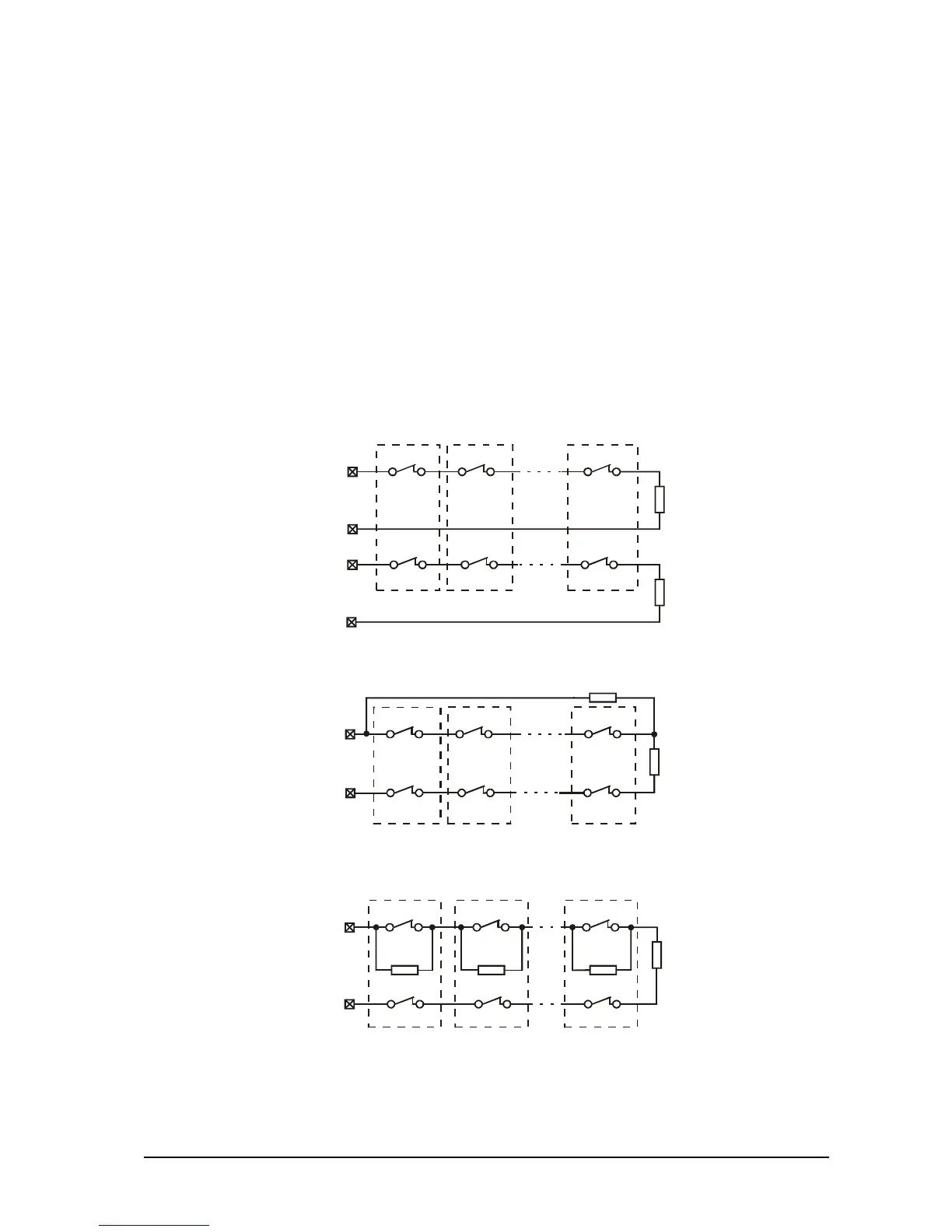
The security system is mounted with sensors with relay contacts. Fire alarm sensors supplied with
relay outputs can also be used.
Use the supplied 1 kΩ resistors to balance the zones. The balancing resistors are installed on the last
sensor of the chain. The zones, which shall not be used, are terminated by way of the 1 kΩ resistor at the
terminals of the CA60Plus Control Panel, irrespective of the chosen type of zone balancing.
After the initial power up of the station, the zone balance type has to be programmed. By default only
1 balancing resistor is used.
Figure 8 shows the possible options for connecting the sensors and for balancing the zones.
Figure 9 shows the connection between a keyswitch and a fire detector with a relay at the base.
The hardware implementation of zone 4 of the panel permits performance in pulse count mode. This
mode counts short pulses – 2 to 4 ms for a period of 20 seconds. The first pulse starts a 20-second
countdown during which pulses are expected to be received. Their number is assigned at Address 28 of
the engineer program. An alarm signal is emitted when this number is reached within the time of 20
seconds. Otherwise the pulse counter will be zeroed after the time of 20 seconds expires.
Activating the pulse count mode will automatically start when a number other than 0 is keyed in at
Address 28 of the engineer program.
b) Connecting Detectors with Two Balancing Resistors
1k
NC
RELAY 1
NC
RELAY 2
NC
RELAY n
NC
TAMPER 1
NC
TAMPER 2
NC
TAMPER n
1k
ZONE x
COM
Fig. 8 Options for connecting detectors to the CA60Plus control panel
а) Connecting Detectors with One Balancing Resistor
NC
RELAY 1
NC
RELAY 2
NC
RELAY n
NC
TAMPER 1
NC
TAMPER 2
NC
TAMPER n
1k
1k
ZONE x
TAMPER
ZONE
COM
COM
C) Connecting up to Four Detectors with Two Balancing Resistors
1k
NC
RELAY 1
NC
RELAY 2
NC
RELAY n
NC
TAMPER 1
NC
TAMPER 2
NC
TAMPER n
1k
ZONE x
COM
1k 1k