CA60Plus control panel Installation manual 5
2. LED60 and LED61 keyboards
Fig.2 CA60Plus LED keyboard
a) Cover
1
2
3
4
5
6
7
89
0
ON
PROG
CLEAR
ENTER
A
R
M
M
E
M
CLR ENT
0
12 3
45 6
78 9
P
R
O
G
D
I
S
A
R
M
б) Bottom
1
1
1
2
1 - Mounting holes
2 - Cables hole
1
1
1
1
1
2
2
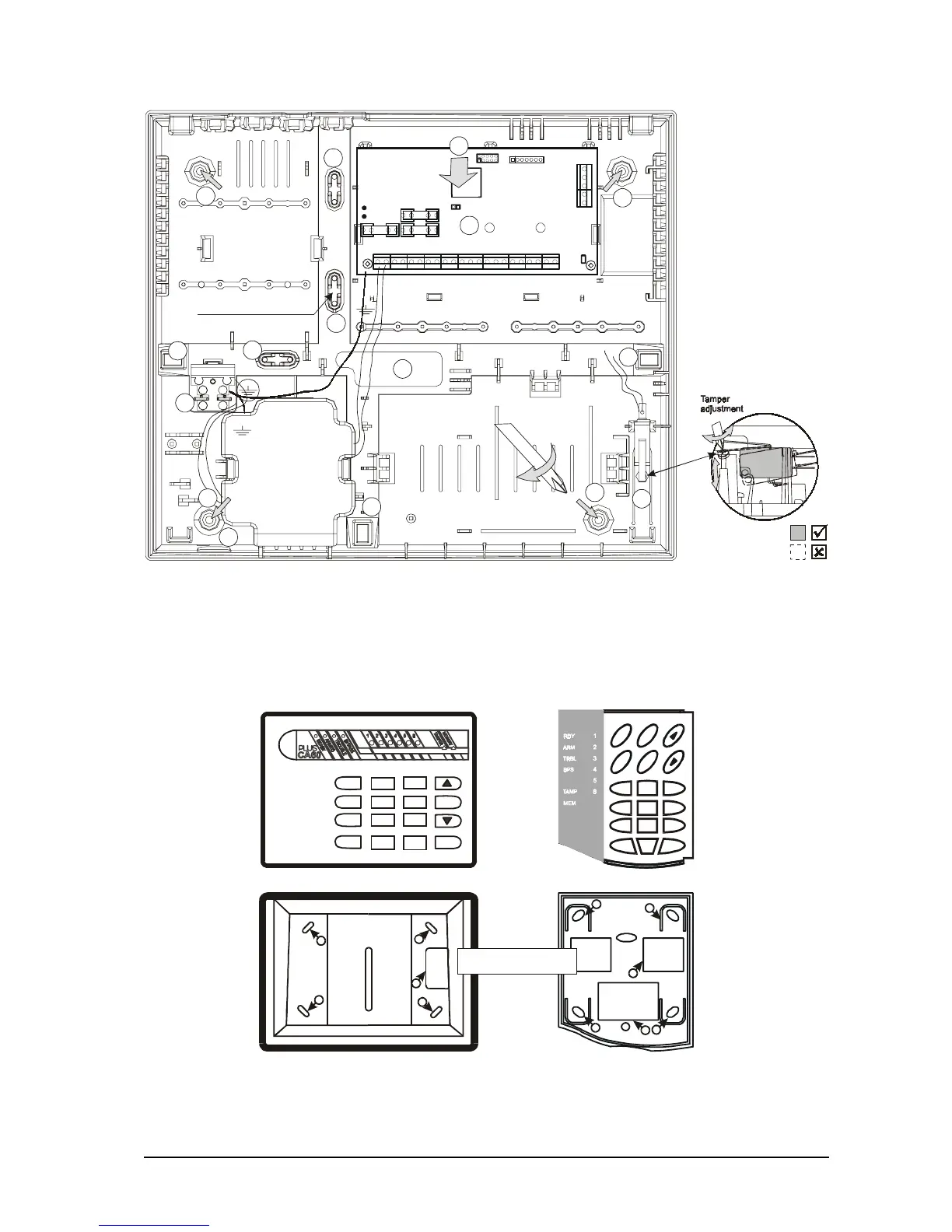
CA60Plus alarm control panel plastic box
Fig.1b CA60Plus control panel plastic box
7
8
6
6
6
6
6
6
5
4
3
2
2
2
2
Accumulator cable
1 - Center support
opening (behind PCB)
2 - S
3 - CA 864 control panel
4 - Mains power supply
terminal
5 - Main cable opening
7 -
8 - Tamper button for box
self-protection
upport opening
6 - Add. cable openings
Mains power supply
opening
Mains
transformer
50 / 60 Hz
15-25 V / 50VA
12V / 7 Ah
battery
Room for additional modules
Room for add. Modules
Use to fix
main power supply cable
F - 0,63 A
BATT
RESET
F1 BATT
F3 AUX
F2 PGM
PROG
Communicator
LED
2A
1A
1A
1
EXPAND