8 CA60Plus control panel Installation manual
5. Using the PGM1, PGM2 and PGM3 programmable outputs
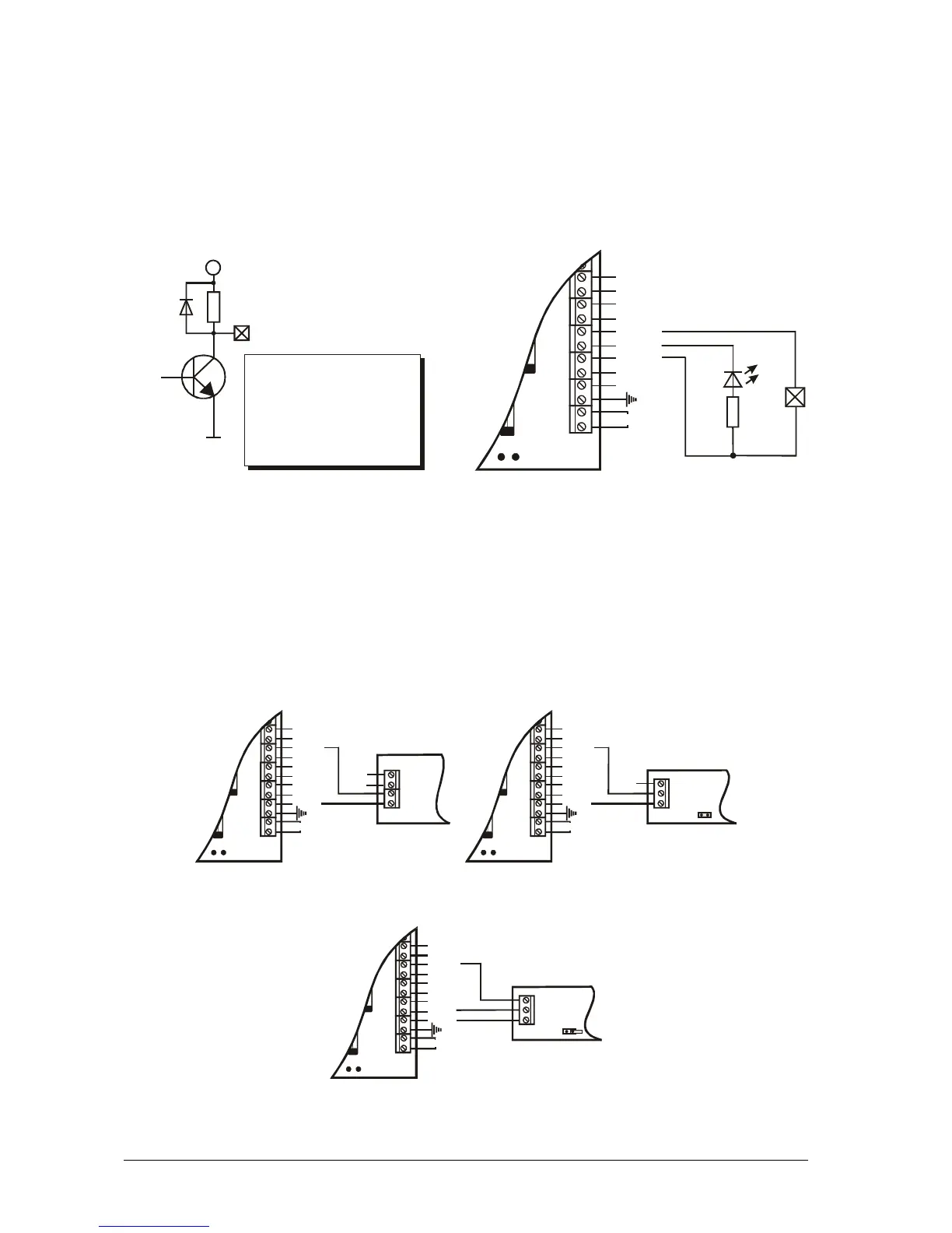
The СА60Plus Alarm Station PGM1, PGM2 and PGM3 outputs have a programmable active level.
This allows them to be used to transmit control signals towards external devices (e.g. a block siren input)
or to directly control low-powered external devices (e.g. relays, LED, etc.). The internal structure of all
PGMs is the same and is shown in Figure 6 a).
Figure 6 b) shows the connection of the relay and a light-emitting diode to the PGM. The active level
of this connection is low.
Fig. 6 b) Controlling light-emitting diode
relay using PGM1 and PGM2 outputs
and
F2
B
AC
+AUX
-AUX
+PGM
PGM1
PGM2
PGM3
SIREN
Z2
COM
CA60Plus
1k
RELAY
LED
Fig. 6 a) Internal structure of programmable
PGMx output
+12 VDC
1 kΩ
PGMx terminal
Permissible current:
- from +12 V - up to 10 mA
- towards GND - up to 100 mA
For SIREN output the
current supplied to GND
is up to 1 A.
6. Using SIREN programmable output
The СА60Plus Alarm Station SIREN output is designed to control a siren. The potential of the active
level of the SIREN output is not being controlled. In inactive state the output will have a potential of +12 VDC,
and in active state – GND. The internal structure is identical to the one shown in Figure 6 a). It should be
pointed out that the transmitter can pass through to GND electricity of up to 1 A.
Fig. 7 shows how to connect SR110E and SR120 sirens using the SIREN output.
Fig. 7 Controlling sirens using SIREN output
F2
B
AC
+AUX
-AUX
+PGM
PGM1
PGM2
PGM3
SIREN
Z2
COM
+12 V
-12 V
CA60Plus
SR110E
a) Connecting SR110E using
a double-wire
F2
B
AC
+AUX
-AUX
+PGM
PGM1
PGM2
PGM3
SIREN
Z2
COM
+12 V
GND
CA60Plus
SR120
BLK
The BLOCK jumper
in
.
SR120 must be
switched on
b) Connecting SR120 using
a double-wire
F2
B
AC
+AUX
-AUX
+PGM
PGM1
PGM2
PGM3
SIREN
Z2
COM
+12 V
GND
CA60Plus
SR120
BLK
The BLOCK jumper
in
.
SR120 must be
removed
c) Connecting SR120 using a triple-wire