12 CA60Plus control panel Installation manual
RESET
PROG
EXPAND
SP
MIC
REC
MSG
PLAY
MSG №
VD60
CA60Plus
BUSY
1
2 2
B1
A1
B
A
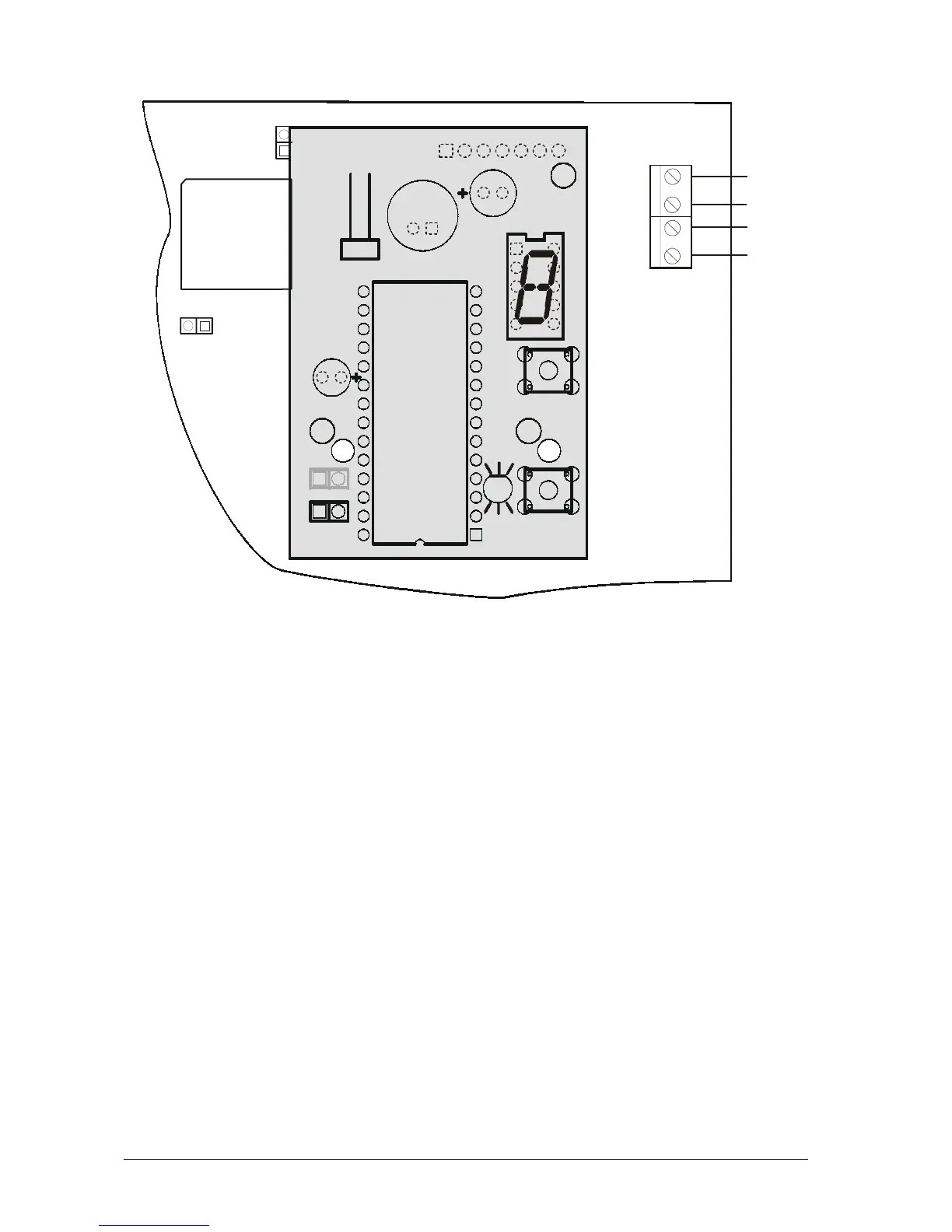
10. Installing the VD60 Voice Telephone Dialer into the СА60Plus
Fig. 12 Installing the VD60 Voice Telephone Dialer
The “VD60” Voice Telephone Dialer module supplements the СА60Plus Alarm Control Panel,
which serves to transmit alarm event messages to the user, under the form of eight pre-recorded voice
messages, of up to 5 sec. each. Two message types are supported – by zone or by event (see Supple-
ment E – Table with Sample Voice Messages).
Turn off the power supply in order to connect the PCB of the voice telephone dialer to the EX-
PAND socket of the CA60Plus Control Panel (1). Fix the PCB onto the pre-mounted plastic spacers
(2). The telephone line should be connected to terminals A and B of the СА60Plus Control Panel.
Polarity need not be observed.
The telephone device can be connected to terminals A1 and B1 of the СА60Plus Control Panel
with no need of observing polarity.
The voice dialer can simultaneously operate with the built-in digital communicator.
The dialer has one LED status indicator – PLAY/RECORD and BUSY, and one single digit LED
display indicating the number of the current message. Use the MSG key to switch-over between
messages. Use the PLAY key to reproduce messages when the REC jumper is turned off, or to
record when it is turned on. A speaker (8-16 ohms) for listening to recorded messages can be con-
nected to the SP socket.
The voice dialer parameters can be engineer programmable.