EasyManua.ls Logo

Telit Wireless Solutions LE910C1-AP - Module Connections; Pin-out Description

Telit Wireless Solutions LE910C1-AP
73 pages
To Next Page IconTo Next Page
To Previous Page IconTo Previous Page
Loading...
LE910Cx mPCIe Hardware Design Guide
1VV0301510 Rev. 13 Page 29 of 73 2021-07-07
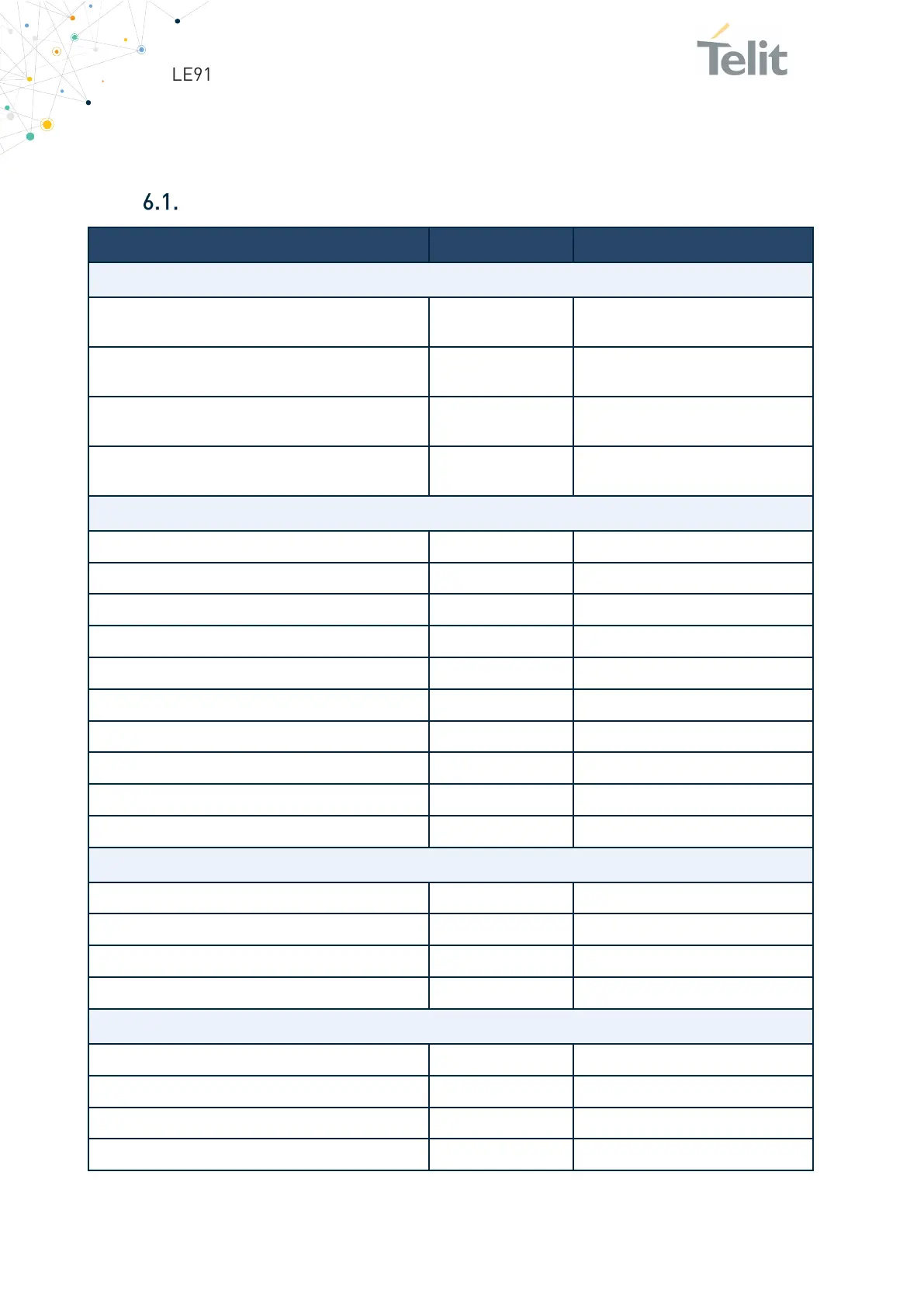
Not Subject to NDA
6. DIGITAL SECTION
Logic Levels
Parameter
Min
Max
ABSOLUTE MAXIMUM RATINGS
Input level on any digital pin (CMOS 1.8) with
respect to ground
-0.3V 2.16V
Input level on any digital pin (CMOS 1.8) with
respect to ground when VBATT is not supplied
-0.3V 0.3V
Input level on any digital pin (CMOS 3.3) with
respect to ground
-0.3V 3.6V
Input level on any digital pin (CMOS 3.3) with
respect to ground when VBATT is not supplied
-0.3V 0.3V
OPERATING RANGE INTERFACE LEVELS 1.8 V CMOS:
Input high level
1.25V
1.95V
Input low level
0V
0.6V
Output high level
1.4V
--
Output low level
--
0.45V
Pull-up resistance
10kΩ
390 [kΩ]
Pull-up resistance
10kΩ
390 [kΩ]
Input capacitance
--
5pF
Low-level input leakage current, no pull-up
- 1uA
--
High-level input leakage current, no pull-down
--
+ 1uA
Drive strength
2mA
16mA
OPERATINGS RANGE INTERFACE LEVELS 3.3 V CMOS:
Input high level
2V
3.3V
Input low level
0V
0.8V
Output high level
2V
--
Output low level
--
0.45V
OPERATING RANGE SIM CARD PADS @ 2.95 V
Input high level
2.1V
3.1V
Input low level
#FIELD!
0.55V
Output high level
2.25V
3.1V
Output low level
0V
0.4V

Table of Contents

Other manuals for Telit Wireless Solutions LE910C1-AP

Related product manuals