LE910Cx mPCIe Hardware Design Guide
1VV0301510 Rev. 13 Page 58 of 73 2021-07-07
9. APPLICATION PCB DESIGN
The LE910Cx-mPCIe modules have been designed to comply with a standard lead-free
SMT process.
Recommended Footprint for the Application
LE910Cx-mPCIe modules fits any full mPCIe 52 pin socket and latch connectors
compliant with PCI Express Mini Card Electromechanical Specification Revision 2.1
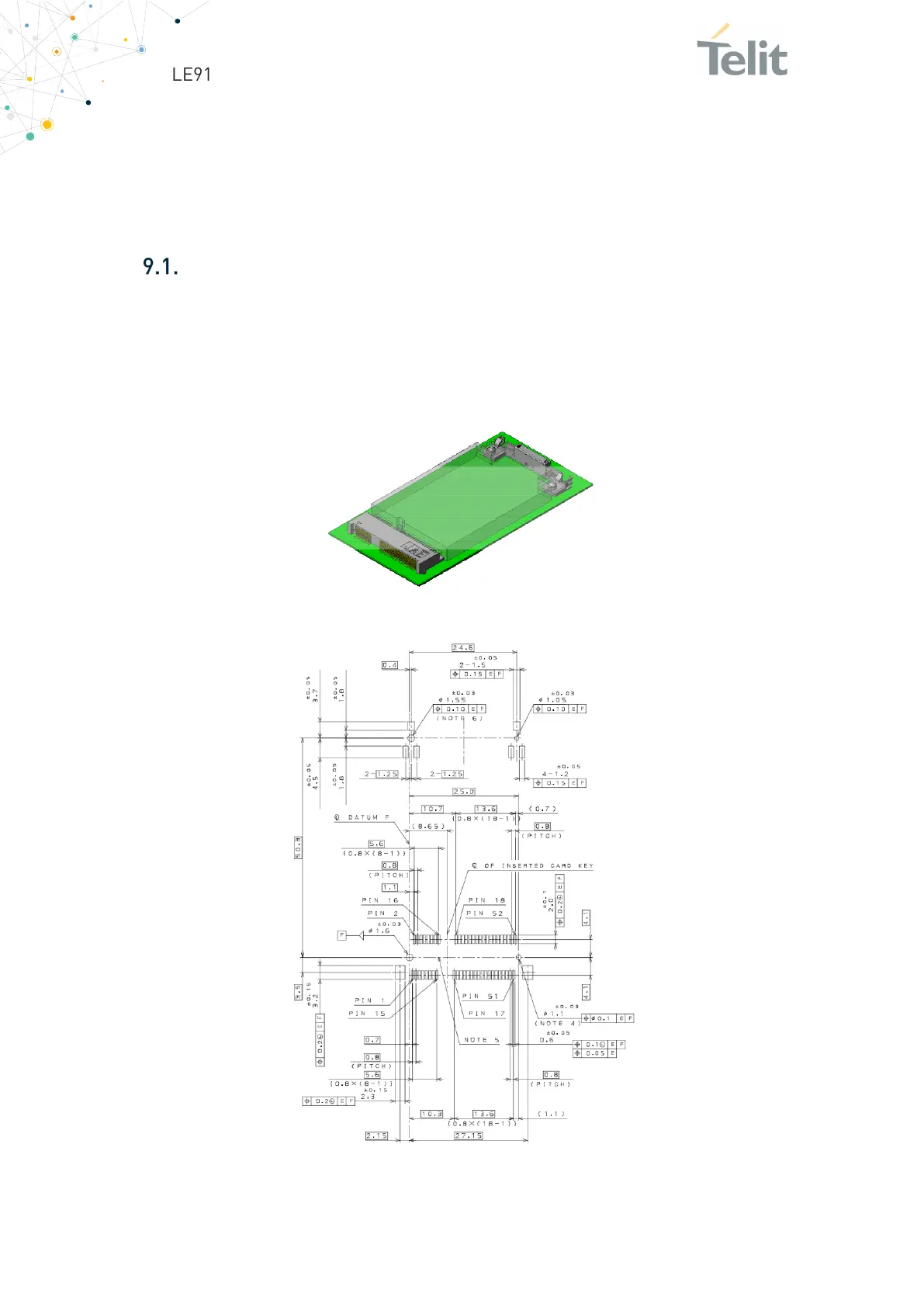
Given below example of board connector (MM60-52B1-E1-R650, JAE) and latch (MM60-
EZH059-B5-R650, JAE) footprint for reference only:
Figure 21:
Board Connector
Figure 22: Latch Footprint
 Loading...


