LE910Cx mPCIe Hardware Design Guide
1VV0301510 Rev. 13 Page 44 of 73 2021-07-07
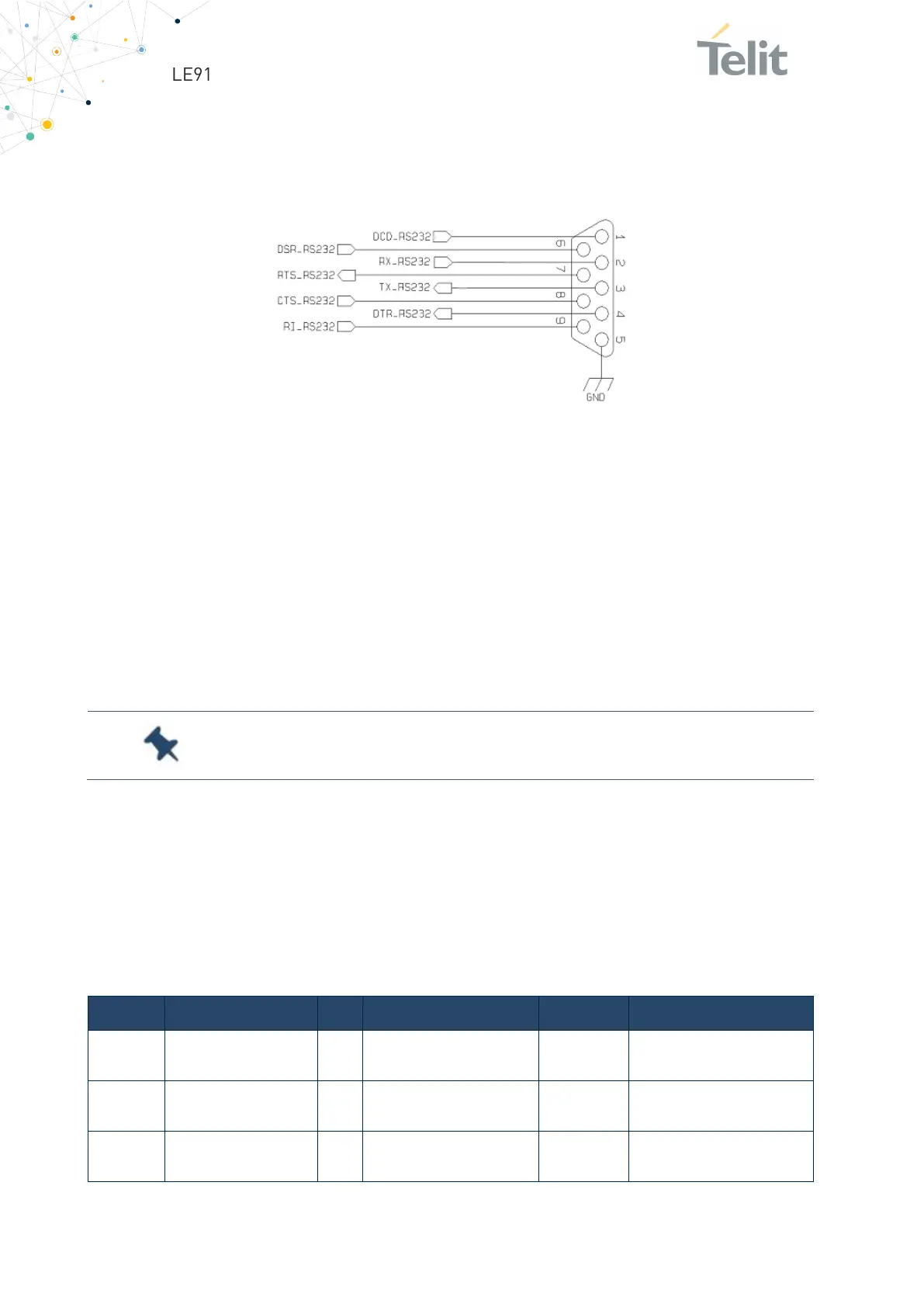
The RS232 serial port lines are usually connected to a DB9 connector as shown in a
Figure below. Signal names and directions are named and defined from the DTE point of
view. RS232 Serial Port Lines Connection Layout:
Figure 13:
RS232 Serial Port Lines
6.6.3. I2C – Inter-integrated Circuit
The LE910Cx-mPCIe supports an I2C interface on the following pins:
• Pin 30 - I2C_SCL
• Pin 32 - I2C_SDA
The I2C can also be used externally by the end customer application.
LE910Cx-mPCIe supports I2C Master Mode only.
Both I2C lines pulled up internally 2.2kΩ to 1.8V.
6.6.4. Digital Audio
The LE910Cx-mPCIe module can be connected to an external codec through the digital
interface.
The product provides a single Digital Audio Interface (DVI) on the following pins:
Digital Audio Interface (DVI) Signals:
PCM_SYNC I/O
Digital Audio Interface
B-PD 1.8V PCM_SYNC
PCM_RX I
Digital Audio Interface
B-PD 1.8V PCM_DIN
PCM_TX O
Digital Audio Interface
B-PD 1.8V PCM_DOUT
 Loading...


