35
Sidekick
®
Plus Test Set
Load Coils
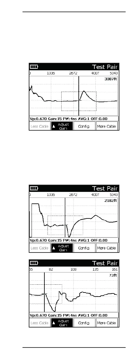
Note: Load coil waveforms look very similar to an open
waveform (see previous illustration). Typically, the load
coil is located at its appropriate spacing, depending on
the loading scheme being used. TDR will not be able to
see past the load coil.
The illustration below shows a typical load coil display.
Bridged Taps/Laterals
Note: If there is more than one bridged tap on the pair,
the additional lateral might be sufficient to obscure the
end of the cable. If necessary, remove the first bridged
tap and retest the cable to locate the next tap.
The illustrations below show single and multiple
bridged taps.