Do you have a question about the Terex FUCHS MHL340 D and is the answer not in the manual?
Describes steps for removing/installing components, requires personnel knowledge of machine functions and safety.
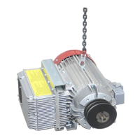
Lists service work covered, including generator installation with wiring and control elements.
Intended for authorized service staff; provides contact for questions.
Details qualifications for service work, distinguishing between disassembly/installation and diagnostics.
Covers increased injury risk, safety through information, and establishing a safe workplace.
Explains signal words (DANGER, WARNING, CAUTION) and symbols for safety instructions.
Provides estimated working time and assembly notes based on experiences.
Details safety precautions for lifting equipment and describes necessary tools like industrial trucks and chains.
Lists required tools and materials for installation, such as rulers, measuring instruments, and Loctite.
Explains designations for viewpoints used in descriptions for orientation purposes.
Instructs on positioning the machine in a suitable, protected area and aligning components.
Details procedure for releasing residual pressure in the hydraulic system using control levers.
Covers steps for safely switching off the machine, including parking brake and key removal.
Advises allowing the machine to cool down to prevent burns from hot engine parts.
Explains that generator installation is described step-by-step, grouped for clarity.
Details removing and reattaching covers and plates to access components for installation.
Provides instructions for cleaning holding surfaces for tensioning pulley support and generator plate.
Lists all necessary parts for generator installation and describes inserting the connection cable.
Covers raising the generator, placing it on the generator plate, and fastening it loosely.
Details installing the V-belt pulley, including cleaning, degreasing, and tightening bolts.
Instructions for Eyebolt removal (13kW) or moving (17kW) to prevent assembly interference.
Describes inserting the generator onto the industrial truck and securing it loosely with hexagon bolts.
Details loosening AC compressor, swiveling it to release V-belt tension, and removing V-belt.
Instructions for fastening the new V-belt pulley, setting the V-belt, and tensioning it.
Covers mounting upper belt tensioner and aligning generator for setting down.
Details mounting lower belt tensioner and aligning generator for setting down.
Describes aligning generator and setting it down after V-belt installation.
Details attaching shielding plate with fastening holes and tightening screws.
Covers tightening generator plate fastenings and generator fastenings to specifications.
Describes setting V-belts in place on engine and generator pulleys.
Details aligning upper tensioning pulley and tightening bolts.
Covers provisional tightening of upper belt tensioner and measuring/adjusting V-belt tension.
Details attaching the cover plate, including edge guard and fastening.
Details placing and tightening the lower belt tensioner.
Lists parts for electrical box and details installing rocker switch in operator panel.
Covers removing screws on control lever carrier and laying connecting cable for electrical box/generator.
Details removing cover, pulling out B55 connection cable, and routing connecting cable in cab.
Describes guiding connection cable through access holes and inserting it into the electrical box.
Covers guiding cable to fastening console, under diesel engine, and under service ladder.
Details guiding cable to generator, inserting plug, securing it, and fastening cable ties.
Lists parts for magnet connection and describes laying magnet cable over boom to coupler socket.
Covers opening hose brackets, guiding magnet cable onto boom, and guiding it on dipperstick.
Details dipperstick cable routing and creating loops for sufficient remaining length.
Covers guiding magnet cable out of dipperstick and closing hose brackets after coupler socket attachment.
Details preparing, setting, and clamping cable ends for the coupler socket.
Covers assignment of cable ends to coupler and retightening socket components.
Covers routing cable from boom down, around swivel motor, and into access hole.
Details guiding cable out of access hole, along service ladder, and under ladder to generator.
Details installing Harting connector, pushing plug inserts, and guiding magnet cable through connection.
Covers fastening Harting connector support, tightening swivel nut, and inserting plug into generator.
Details checking magnet cable and inserting air hose through uppercarriage and generator plate.
Explains cable routing variations for multi-purpose stick and laying magnet cable over boom.
Describes parts required for Quick Connect and cable guiding variations for optional equipment.
Explains where the enable code is indicated and how to enable the option.
Covers checks for electrical functioning of magnet system and safety devices before powering on.
Provides warnings about uncontrolled movements and steps for starting the engine and generator.
Provides technical data for the generator, including weight.
Lists tightening torques for various screw sizes, applicable when not specified elsewhere.
Identifies the 'Optik 1' measuring instrument for V-belt tension.
References to service documentation and operating instructions.
| Brand | Terex |
|---|---|
| Model | FUCHS MHL340 D |
| Category | Multi Terrain Loaders |
| Language | English |