Chapter 2 – Installation
TestEquity 1007C Temperature Chamber Page 2-3
Input Power Configuration
Overview
This chamber is designed to be easily configured for operation from a Single Phase or Three
Phase power source, and either 208 V / 60 Hz or 230 V / 60 Hz. Other input voltages and 50 Hz
operation are available as special options, and are not covered in these instructions.
Your chamber was configured prior to shipment for the particular voltage that was specified at
time of order. These instructions should be used to verify the input voltage configuration prior to
installation, or to change the input voltage from one configuration to another.
! CAUTION: The Input Voltage label on the back of the chamber indicates the input voltage
configuration as shipped from the factory. If the input voltage configuration is
changed, this label must be replaced to reflect the new configuration.
Replacement labels are available from TestEquity at no charge.
! CAUTION: This chamber must be properly configured for either 208 V or 230 V nominal
input. 208 V and 230 V are NOT the same. Do NOT guess! Do NOT assume
you have “220 V”. You must verify the exact type of electrical service you
have. If there is any doubt, you must consult with a qualified electrician who
is familiar with industrial plant wiring. In addition, the input line voltage
should be measured while the chamber is operating in the COOL mode to
ensure that the expected nominal voltage of either 208 V –5/+10% or 230 V
±10% is present. Operation below 198 V or greater than 253 V requires
internal transformers, which can be supplied for a nominal charge.
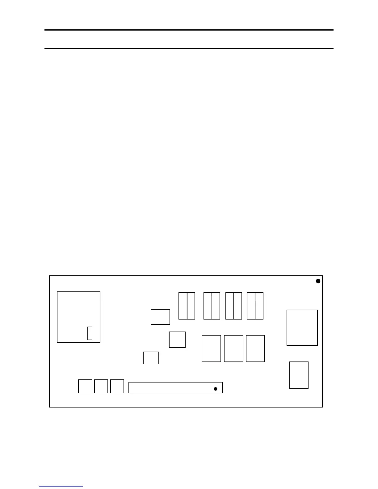
Figure 2-1 – Location of Input Configuration Terminals on the Electrical Sub Panel