Chapter 9 – Maintenance
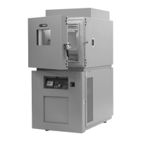
Page 9-6 TestEquity 1007C Temperature Chamber
How to inspect the electrical compartment.
1. Disconnect the chamber from the power source.
2. Turn the Main Disconnect Switch to the OFF position.
3. Remove the lower door retaining screw located on the right side. Open the lower door.
4. Check for loose components, loose wires, burned insulation near terminals, and burned or
excessively pitted contacts on contactors.
How to clean the condenser.
1. Disconnect the chamber from the power source.
2. Turn the Main Disconnect Switch to the OFF position.
3. Remove the lower door retaining screw located on the right side. Open the lower door.
4. Clean the condenser and desuperheater fins with a vacuum cleaner.
NOTE: You may need to clean the condenser more frequently if the chamber is in a dusty
environment. You may be able to clean the condenser less frequently if the chamber is in a very
clean environment.
How to verify the calibration.
TestEquity recommends verifying the calibration before attempting to actually perform a
calibration. The state-of-the-art instrumentation used in TestEquity chambers is of the highest
quality and seldom goes out of calibration. If you try to calibrate the instrumentation before
determining that calibration is necessary, you may make it worse if done incorrectly.
Variations in temperature throughout the chamber interior is NOT a measurement of accuracy.
These variations, called “gradients”, are a function of the physical design of the chamber and its
airflow, the characteristics of the test sample, and how it is oriented in the chamber. You cannot
“calibrate” to improve gradients. The correct way to adjust what the temperature controller
“displays” compared to what is measured at some point other than the controller’s sensor, is with
the “Calibration Offset” parameter. See page 6.2 of the “Series F4 User’s Manual” for details.
Calibration verification should be performed with the Calibration Offset set to 0.0 (zero).
The F4 Temperature Controller accuracy is specified ±1.55°C (above –50°C) and ±1.66°C
(below –50°C). Total system accuracy in the chamber includes the controller plus the
thermocouple wire accuracy of ±1.0°C. Total system accuracy over the chamber’s operating
range is can be as much as ±2.66°C, although it is typically better than ±1.0°C.
The easiest way to verify the instrumentation accuracy is with an independent calibrated
temperature sensor and display. Place the sensor near the chamber’s sensors, which are located
towards the right side of the conditioner fan grille. If the readings agree within the specified
limits above, then no calibration adjustments are necessary.
If calibration of the temperature controller is necessary, refer to page 9.2 of the “Series F4 User’s
Manual” and follow the instructions for “Thermocouple Input Procedure”. Theory of Operation