21
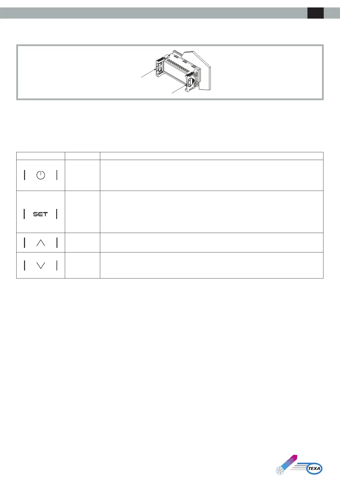
The device is designed for panel mounting using the supplied snap-on brackets. The thickness of the panel must be between 0.8 and 2.0 mm (1/32 and
1/16 in).
3. User Interface
3.1 Keypad
3.1.1 Key Functions
The following table illustrates the functions of the device’s keys:
Key Name Function
ON/Stand-by
• Alongpressturnsthedeviceonoroandreturnstothemainscreenifaninternalmenuiscurrently
displayed
• A short press during parameter setting cancels the editing and acts as the “back” key
SET
• A long press enters the settings menu
• A short press enters the Set Point menu directly (Set Menu)
• Asinglepressconrmstheedit
• In menu navigation, it acts as the “Enter” key
UP
• A short press moves around the menu
• Alongpressfromthemainscreenresetsthelterhourscounter
DOWN
• A short press moves around the menu
• A long press from the main screen locks (Loc) / unlocks (UnL) the keypad
3.1.2 Testing Sequence from Keypad
The testing sequence is activated by entering the testing menu CoL and setting the parameter to ON.
The phases of the testing sequence are given below:
1) Check that the digital input IN4,conguredas“Genericalarm(NO)” is closed.
2) Activation of the evaporator fan (PUM).
3) Activation of the compressor (COM).
4) Activation of the condensing fan (PUM).
5) After activation of the condensing fan, the two fans and the compressor remain active for 3 minutes.
6) Once 3 min has passed, the testing sequence concludes.
The sequence can be concluded before this by the operator by opening the digital input IN4 (by opening the external contact between Pins 4-5 of the
alarmsconnector).Byopeningthisdigitalinput,allloadsareshutoandthealarmrelayDO1 switches (between Pins 1-2-3 of the alarms connector). The
operator then recloses the digital input IN4 and the regulator exits the testing sequence.
ENG