25
5.2 I/O Connections
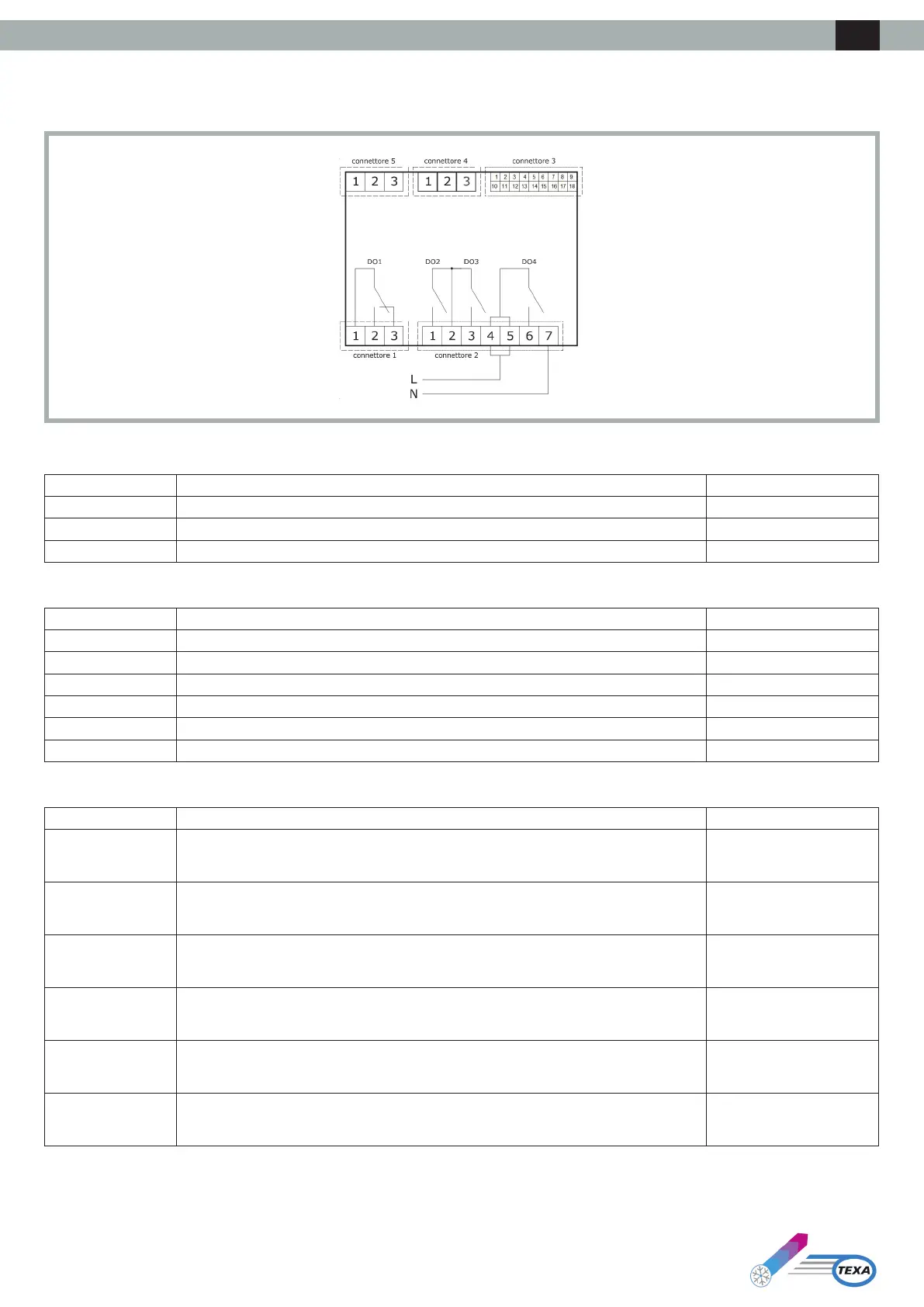
The following drawing illustrates the layout of the I/O connections of the electronic board:
The following table illustrates the meaning of CONNECTOR 1:
Part Meaning Function
1 Digital output DO1: common [C1] Alarm
2 Digital output DO1 (8 A SPDT): normally open [NO1] Alarm
3 Digital output DO1 (8 A SPDT): normally closed [NC1] Alarm
The following table illustrates the meaning of CONNECTOR 2:
Part Meaning Function
1 Digital output DO2 (8 A SPST): normally open [NO2] Evaporator fan
2 Relay digital output DO2 and D03: common [C23]
3 Digital output DO3 (8 A SPST): normally open [NO3] Condensing fan
4-5 Digital output DO4 (16 A SPDT): board supply common (115-230 VAC isolated) [L-C4]
6 Digital output DO4 (16 A SPDT): normally open [NO4] Compressor
7 Board supply (115-230 VAC isolated) [N]
The following table illustrates the meaning of CONNECTOR 3:
Part Meaning Function
1 Analogue output AO1 (0-10 V/ PWM)
2 Analogue input IN1 (DI / NTC / 4-20 mA / 0-10 V / 0-5 V) Condensation temperature /
pressure
3 Analogue input IN2 (DI / NTC / 4-20 mA / 0-10 V / 0-5 V) Intake sensor (internal
temperature) REGULATION
SENSOR
4 Analogue input IN3 (DI/NTC) External temperature sensor
5 Analogue input IN4 (DI/NTC) Generic alarm (door
microswitch contact)
6 Analogue input IN5 (DI/NTC) Phase sequence relay
ENG