24
5. Electronic Board
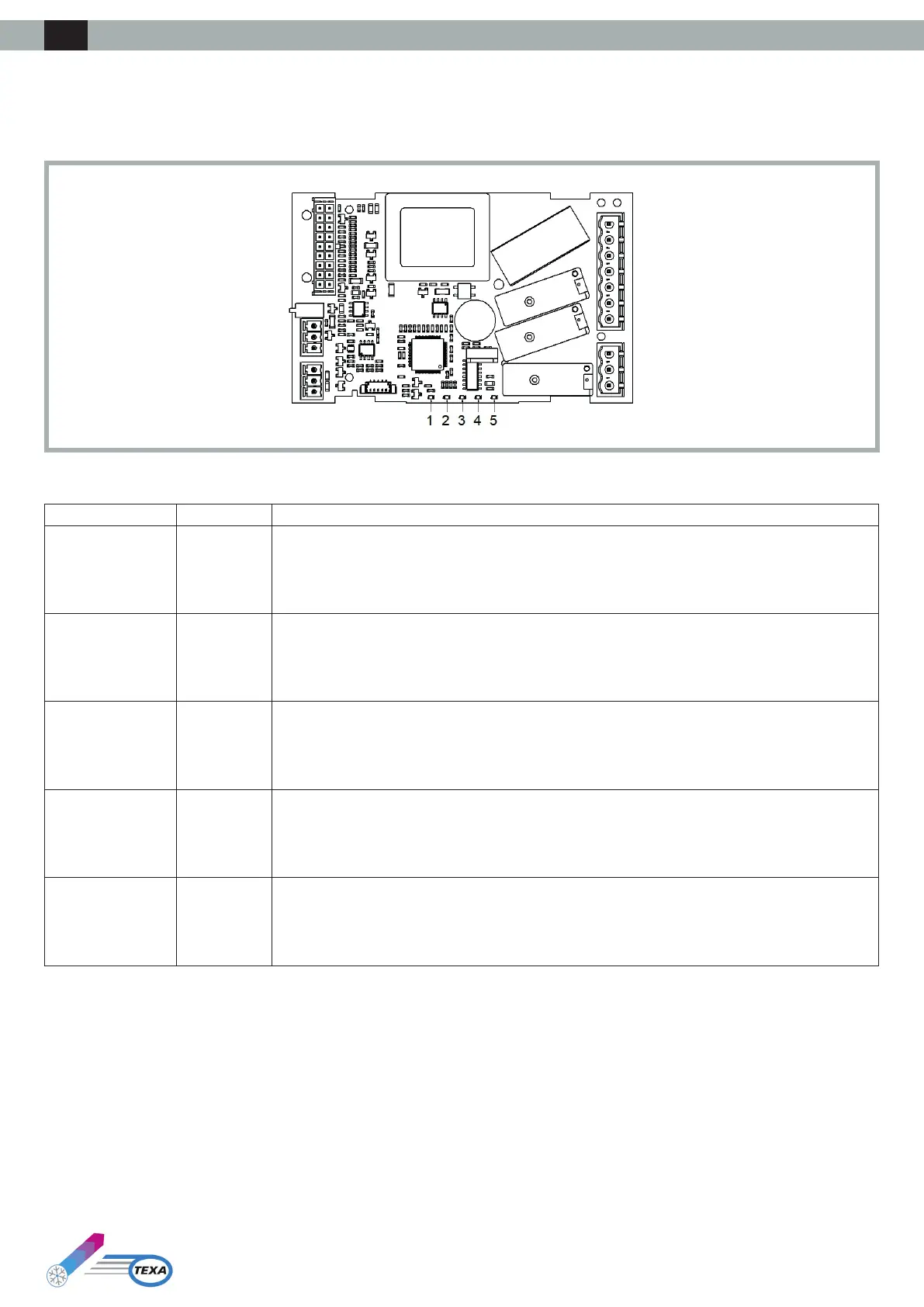
5.1 LED Indicators Layout
The following drawing illustrates the layout of the LED indicators of the electronic board:
The following table illustrates the meaning of the LED indicators of the electronic board:
LED no. Colour Meaning
1 GREEN
POWER LED
- ON if the controller is powered
- OFF if the controller is not powered
2 GREEN
LED RUN
- ON if the regulation is active
- OFF if the regulation is not active
3 RED
ALARM LED
- ON if one manual reset alarm is active
- BLINK if an automatic reset alarm is active
- OFF if no alarm is active
4 AMBER
INTRABUS LED
- ON if a non-functioning Sequencing communication is in progress between two air conditioners
- BLINK if a Sequencing communication is in progress between two air conditioners
- OFF if no Sequencing communication is in progress
5 AMBER
RS-485 LED
- BLINK if an RS-485 communication is in progress
- OFF if no communication is in progress
ENG