25
23
19
18
22
27
20
21
17
18
28
Stop Start Repeated
Start
Stop
I2C[x]_SDA
I2C[x]_SCL
16
26
24
10
8
4
3
7
12
5
6
14
2
3
13
Stop Start Repeated
Start
Stop
I2C[x]_SDA
I2C[x]_SCL
1
11
9
AM3359, AM3358, AM3357, AM3356, AM3354, AM3352
SPRS717H –OCTOBER 2011–REVISED MAY 2015
www.ti.com
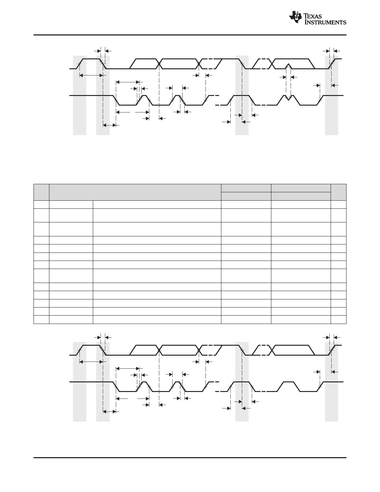
Figure 7-68. I
2
C Receive Timing
Table 7-70. Switching Characteristics for I
2
C Output Timings
(see Figure 7-69)
STANDARD MODE FAST MODE
NO. PARAMETER UNIT
MIN MAX MIN MAX
15 t
c(SCL)
Cycle time, SCL 10 2.5 µs
Setup time, SCL high before SDA low (for a repeated
16 t
su(SCLH-SDAL)
4.7 0.6 µs
START condition)
Hold time, SCL low after SDA low (for a START and a
17 t
h(SDAL-SCLL)
4 0.6 µs
repeated START condition)
18 t
w(SCLL)
Pulse duration, SCL low 4.7 1.3 µs
19 t
w(SCLH)
Pulse duration, SCL high 4 0.6 µs
20 t
su(SDAV-SCLH)
Setup time, SDA valid before SCL high 250 100 ns
21 t
h(SCLL-SDAV)
Hold time, SDA valid after SCL low 0 3.45 0 0.9 µs
Pulse duration, SDA high between STOP and START
22 t
w(SDAH)
4.7 1.3 µs
conditions
23 t
r(SDA)
Rise time, SDA 1000 300 ns
24 t
r(SCL)
Rise time, SCL 1000 300 ns
25 t
f(SDA)
Fall time, SDA 300 300 ns
26 t
f(SCL)
Fall time, SCL 300 300 ns
27 t
su(SCLH-SDAH)
Setup time, high before SDA high (for STOP condition) 4 0.6 µs
Figure 7-69. I
2
C Transmit Timing
192 Peripheral Information and Timings Copyright © 2011–2015, Texas Instruments Incorporated
Submit Documentation Feedback
Product Folder Links: AM3359 AM3358 AM3357 AM3356 AM3354 AM3352
 Loading...