• Communication Direction: Toggles between north and south, indicates direction of auto-addressing and
tone propagation. In this release of the GUI, ensure that North is selected.
• Low Pass Filtering: Sets the cutoff frequency of the post-ADC digital filter for both cell and bus bar voltage
measurements.
• Sampling Type: Toggles between single and continuous ADC run modes.
• AUX ADC: Enables AUX ADC continuous run mode to enable a valid BAT voltage measurement.
In Single run mode, each press of the Start Polling button updates the cell measurements just once. In
Continuous mode, the cell measurements updates automatically at the selected refresh rate once polling has
started.
3.3 Measurement Display
The measurement display is where voltage and temperature measurements can be found. Under the Cell
Voltage tab, all 16 cell measurements can be monitored along with battery module voltage (if the resistor ladder
is in use, this is the supply voltage) and bus bar voltage. The user also has the option to display the unconverted
hexadecimal values from the corresponding VCELL*_HI/LO registers or the unfiltered cell measurements. The
user can customize which of these items to display at any time using the Manage Columns window to select
and deselect each cell. The user can display a cell balancing status indicator. If the Faults column is selected,
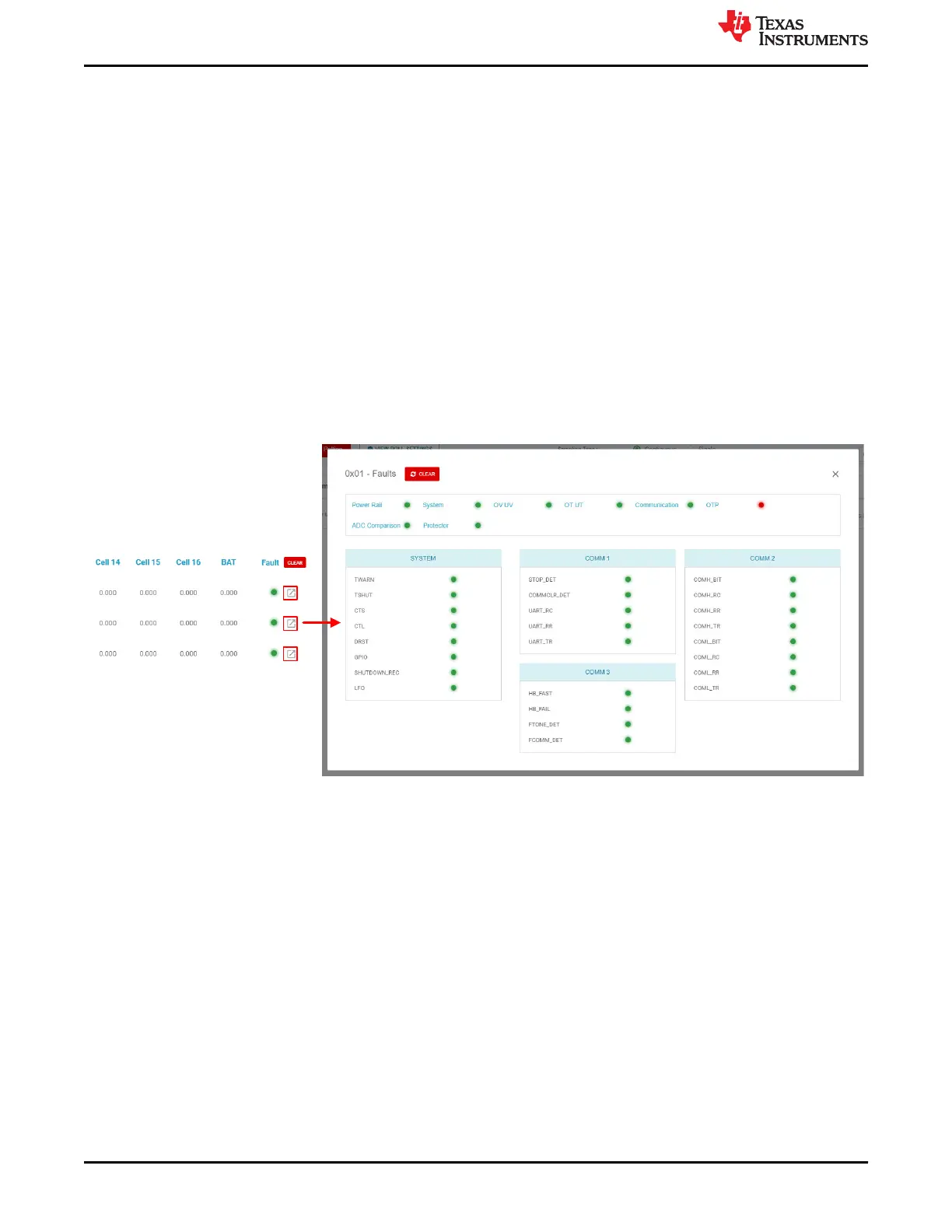
clicking on the pop-up button next to the status light displays a detailed fault summary for each device.
Click on pop-up
button to access Fault
window for device
Figure 3-3. Device Fault Display in Cell Monitoring Page
Upon waking the device and running auto addressing, the user can expect to see the following faults:
• FAULT_SYS[DRST]: Triggered because of power on reset (POR)
• FAULT_POWER3[AVDDUV_DRST] & [AVDDREFUV_DRST]: Triggered because of POR
• If multiple devices are connected, FAULT_COMM3[FCOMM_DET]: Device detects faults in devices further up
the stack. This fault does not trigger for the device at the top of the stack. (This can be disabled by using the
Embedded Fault checkbox at the top of the menu to the right of the display hex values toggle button)
Clear faults by clicking the Clear button at the top of the fault display and start polling to update the fault and
status lights. All of the fault lights should be green with the possible exception of the OTP fault, which triggers if
polling has been run since the polling sequence sets the number of active cells. To mask this fault on a single
device, you can either select the Set button (Mask CUST_CRC) at the top of the menu or navigate to the
Register Map page, search for the register FAULT_MSK2, and change bits MSK_OTP_CRC and
MSK_OTP_DATA to 1. To mask this fault for multiple connected devices, perform a broadcast write from the
Debug page using the following data:
• Initialization byte: 0xD0
• Register Address: 0x11
Cell Monitor
www.ti.com
14 BQ79616-Q1 and BQ75614-Q1 GUI User's Guide SLUUC36 – DECEMBER 2020
Submit Document Feedback
Copyright © 2020 Texas Instruments Incorporated
 Loading...