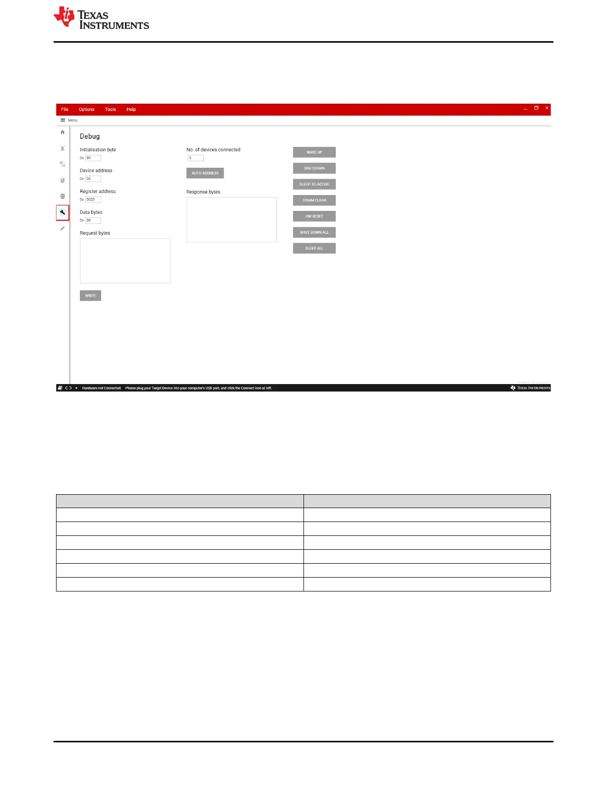
EasyManua.ls Logo

Texas Instruments BQ79616-Q1 User Manual

Texas Instruments BQ79616-Q1
29 pages
To Next Page IconTo Next Page
To Previous Page IconTo Previous Page
Page #27 background imageLoading...
Page #27 background image
11 Debug
From this page, the user can directly perform register reads and writes to the connected devices. This provides
some extended functionality that is not present on the GUI front end.
Figure 11-1. BQ79616 GUI Debug Page
11.1 Write and Read
The first step in communicating with the device is to use the initialization byte that corresponds to the intended
communication type. A summary of the different initialization bytes available to the user can be found in the table
below.
Table 11-1. Initialization Bytes
Communication Type Initialization Byte
(1)
Single Device Read 0x80
Single Device Write 0x9*
Stack Read 0xA0
Stack Write 0xB*
Broadcast Read 0xC0
Broadcast Write 0xD*
(1) For write operations, replace asterisks with the number of bytes to be written minus one up to a maximum of 8 bytes written
simultaneously.
Second, the user specifies the device to be communicated to via the Device Address field. This field is only
available for single device communication, as the stack and broadcast communication modes communicate to
multiple devices. Third, the user specifies the Register Address to be written to. Last, the user fills out the Data
Bytes field. For a read, the data bytes should be the number of bytes to be read minus one. For a write, the data
bytes are the bytes to be written.
For both reads and writes, the user should then press the Write button. For read commands, a write button
press also performs a read from the device, and the response is populated in the response bytes window.
www.ti.com
Debug
SLUUC36 – DECEMBER 2020
Submit Document Feedback
BQ79616-Q1 and BQ75614-Q1 GUI User's Guide 27
Copyright © 2020 Texas Instruments Incorporated
Question and Answer IconNeed help?

Do you have a question about the Texas Instruments BQ79616-Q1 and is the answer not in the manual?

Texas Instruments BQ79616-Q1 Specifications

General IconGeneral
BrandTexas Instruments
ModelBQ79616-Q1
CategoryRecording Equipment
LanguageEnglish

Summary

Getting Started

Installing the GUI

Step-by-step instructions for installing the graphical user interface software.

Uninstalling and Updating GUI

Procedures for removing previous GUI versions and installing the latest update.

Installing GUI Composer Runtime

Guidance on installing the necessary runtime environment for the GUI application.

Updating USB2ANY Firmware

Crucial steps to update the USB2ANY firmware for correct GUI operation and error prevention.

Starting Up the EVM

Outlines the connection and power-up sequence for the BQ79616EVM evaluation module.

BQ79600-Q1 Device Key Differences

Highlights specific operational differences for the BQ79600-Q1 EVM with the GUI.

BQ79631-Q1 Device Key Differences

Details specific operational differences for the BQ79631-Q1 EVM with the GUI.

GUI Home Page

GUI Home Page Overview

Introduces the main GUI screen, navigation, and initial setup guidance.

Cell Monitor

Starting up the Device

Steps to wake up, auto-address, and start polling devices for cell monitoring.

Cell Monitor Settings

Configuration options for cell measurements, including refresh rate and direction.

Measurement Display

Explains how to view cell voltages, temperatures, and fault status details.

GPIO/Temperature Tab

Details on viewing GPIO voltages and die temperatures via the GUI.

Detailed Device View

Provides an in-depth view of individual device parameters, status bits, and plots.

Cell Balancing

Balancing Timetable

Setting timers for cell balancing operations and managing timing profiles.

Balancing Sequence

Configuring auto and manual cell balancing modes and sequences.

Thresholds

Setting voltage (VCBDONE) and temperature (OTCB) thresholds for balancing control.

Start Balancing

Initiating, pausing, and resuming the cell balancing process.

Protector

Threshold Settings

Configuring overvoltage, undervoltage, overtemperature, and undertemperature protection thresholds.

Protector Run Modes

Selecting protector evaluation modes like Round Robin or Single Channel Run.

Communication Control

Communication Configuration

Settings for communication timeouts, holdoff, and debug modes.

Control Register and Tones

Sending tones and modifying control registers for device communication.

Diagnostics

System Diagnostics Overview

Introduction to system-level diagnostics for ASIL rating, including ADC setup.

Command Sequence

Command Sequence Tab

Creating, organizing, and executing custom command scripts and sequences.

Faults

Faults Tab Overview

Viewing current device faults and using the interface to mask or reset them.

Register Map

Register Display

Viewing and editing device registers with addresses, values, and bit fields.

Register Read

Methods for reading individual or all registers, including auto-read functionality.

Debug

Write and Read

Performing direct register reads and writes for extended debugging functionality.

Current Sensing

Current Sensing Measurements

Steps for taking current sense measurements using SRP/SRN pins via the GUI.

Troubleshooting

Common Issues

Addresses frequent problems like GUI connection errors and unresponsiveness.

Best Practices

Recommended procedures for ensuring proper communication and data updates.