propagable, meaning that a tone is not generated to the next device in the stack. Therefore, to shutdown or reset
all connected devices, all CONTROL1 registers must be written to.
This tab also features other relevant tones and CONTROL1 bits. All buttons on this tab are grouped by general
function: wake, shutdown, reset, sleep, and communication. Variations of each function exist to allow greater
flexibility in controlling the connected devices.
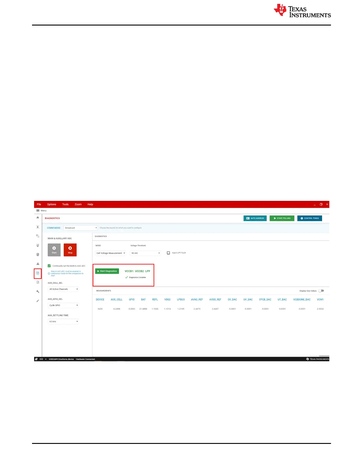
7 Diagnostics
The Diagnostics tab provides the user a sneak preview into the workings of the system level diagnostics that the
BQ devices provide. These are highly important functions for designing a safe, ASIL rated system.
On the left hand side, there are start/stop buttons that turn on/off the MAIN & AUX ADCs that are both required
to be ON for the device to allow diagnostics to be completed. Below the start/stop buttons are AUX ADC settings
that the user can configure to lock to certain channels, gpios, or change the settling time.
After the user has started the main/aux adcs and set desired aux settings the user can select a diagnostic mode
in the dropdown above the green "start diagnostics" button. As an example, the Cell Voltage Measurement
diagnostic is shown below. This diagnostic will do a simple comparison between the Main ADC voltage level and
the AUX ADC level for the selected AUX channel(s). Once the user selects their desired voltage threshold,
select green"Start Diagnostics" button which will either trigger a notification that the diagnostic completed or
aborted. See the BQ79616-Q1 datasheet for details on abort conditions. If the diagnostic completed, it will
update the VCCB1, VCCB2, LPF text to red or green. Green meaning that there are no failures in the
corresponding register and red indicating that there are failures. Hover over VCCB1 to see the linked register
(FAULT_COMP_VCCB1). If the VCCB1 text is red, then the user can then navigate to the register map and
search for FAULT_COMP_VCCB1 to see the exact bit level cell failures.
Figure 7-1. Diagnostics Tab
Diagnostics
www.ti.com
22 BQ79616-Q1 and BQ75614-Q1 GUI User's Guide SLUUC36 – DECEMBER 2020
Submit Document Feedback
Copyright © 2020 Texas Instruments Incorporated
 Loading...