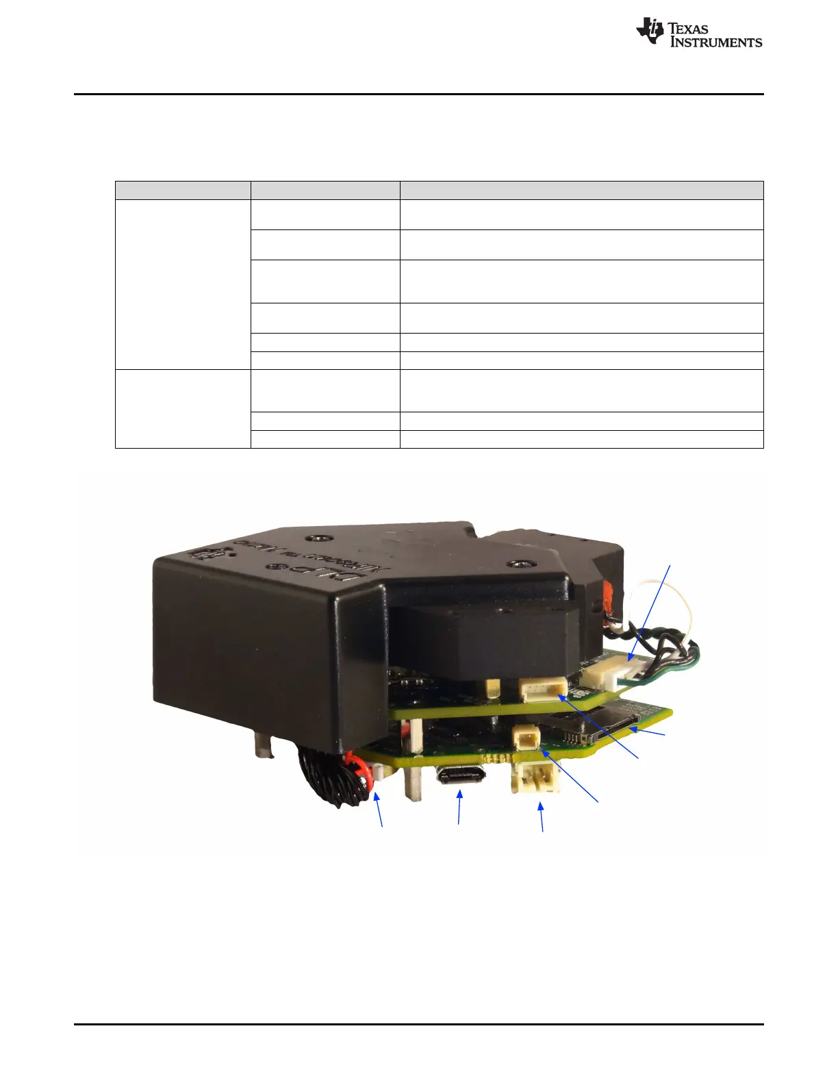
microSD
Battery
USB
Lamp
Battery
Thermistor
Lamp
Photodetector
Detector
What is the DLP NIRscan Nano EVM?
www.ti.com
1.2.3 Connections
Table 1-3 lists the DLP NIRscan Nano connectors with its locations shown in Figure 1-4 and Figure 1-5.
Table 1-3. DLP NIRscan Nano Connectors
BOARD SCHEMATIC LABEL DESCRIPTION
Micro-USB connector: Provides power and PC connectivity with HID
J1
commands
Detector board interface: Provides Tiva's SSI1 connection to ADS1255
J2
and Tiva's I2C7 to TMP006
Expansion connector: Provides TIva's UART4 or SSI0 interface to
J3 external device. UART4 is used as Tiva's console output for debugging
Microcontroller board
information
JTAG connector: ARM Cortex 10-pin emulation (XDS100, XDS200, or
J4
XDS560) connection
J6 Lithium-Ion or Lithium-Polymer battery connection
J7 Battery thermistor connection
Trigger connector. This connector is covered by the top cover. Access to
J500 this connector requires to removal of the Microcontroller and DLP
controller boards from the optical engine
DLP controller board
J501 Lamp photodetector connector
J503 Lamp power connector
Figure 1-4. DLP NIRscan Connectors (Rear View)
14
DLP NIRscan Nano Overview DLPU030B–June 2015–Revised July 2015
Submit Documentation Feedback
Copyright © 2015, Texas Instruments Incorporated